Hanging tool for hung conveying spraying line

A spraying line and hanger technology, applied in conveyors, transportation and packaging, load hanging components, etc., can solve problems such as affecting the appearance of paint film adhesion, reducing the production efficiency of spraying lines, and increasing daily maintenance work. The effect of avoiding ineffective cleaning work, small daily maintenance workload and low manufacturing cost

Active Publication Date: 2014-03-05
CHONGQING FUJI MACHINE MFG
View PDF8 Cites 20 Cited by
  • Summary
  • Abstract
  • Description
  • Claims
  • Application Information

AI Technical Summary

Problems solved by technology

Therefore, during use, the end face of the nut is affected by the gravity of the hanger and the workpiece to form a large frictional resistance and impact tension and compression with the hanger or the main part. Long-term use may cause the hanger and workpiece to fall due to loosening or falling off of the nut. potential safety hazards falling, or to increase daily maintenance work to eliminate hidden dangers, even if a locking pin with a cotter pin structure is installed between the nut and the hanging head rod, it will also cause
In addition, the spraying line using the hanging conveyor is usually equipped with a heating and drying process after the spraying process. The grease of the conveying chain decreases in viscosity and drips in the drying heating environment, thereby polluting the product. The grease of this kind Drip flow may occur during paint spraying or after paint spraying. Regardless of whether it occurs before or after spraying, it is necessary to clean the contaminated parts, otherwise it will affect the adhesion of the paint film or the appearance of the product sprayed. There are defects that reduce the production efficiency of the spraying line

Method used


Image

  • Hanging tool for hung conveying spraying line
  • Hanging tool for hung conveying spraying line
  • Hanging tool for hung conveying spraying line

Examples


Embodiment 1

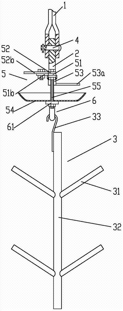
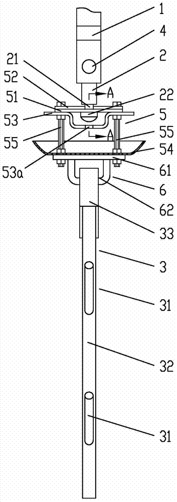
[0027] Example 1 see figure 1 , figure 2 , image 3 , Figure 4 , Figure 5 , Image 6, a hanger used for hanging and conveying a spraying line, comprising a hanger 1, a hanger head 2, and a hanger body 3, the hanger body 3 is provided with two hanging arm groups, and the hanging arm group has two circumferentially symmetrically distributed hanging arms arm 31, the hanging head 2 is connected to the hanging clip 1 through a pin shaft 4 arranged horizontally, the lower part of the hanging head 2 is integrally formed with a journal 21 having a structure of a terminal 22, and the hanging head 2 passes through the shaft The neck 21 and the end 22 are coaxially connected to a hanging basket 5, and the lower end of the hanging basket 5 is connected to the hanger main body 3; the hanging basket 5 includes a beam connected to the hanging head 2, and the beam passes through two ends The connecting screw 55 is connected with an open container-like basket 54; the crossbeam consists...

Embodiment 2

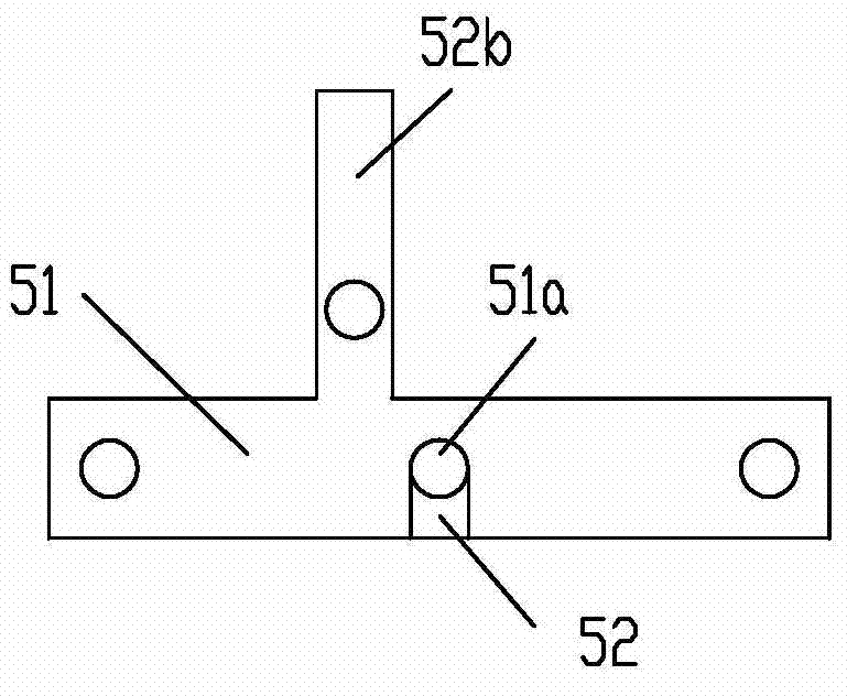
[0029] Example 2 see Figure 7 , Figure 8 , the first crossbeam 51 and the second crossbeam 52 are a left-right combination structure, the main bodies of the first crossbeam 51 and the second crossbeam 52 are strip-shaped, and the two ends of the first crossbeam 51 are provided with a The through hole of the screw rod 55; the middle part of the first beam 51 forms a strip-shaped gap, and the semicircular opening on the first beam 51 is located at the bottom of the gap; the second beam 52 is located in the gap, and the second beam 52 is located in the gap. 52 and the first crossbeam 51 are fixedly connected by bolts and nuts, and the other semicircular opening is formed on the inner side wall of the second crossbeam 52, and two semicircular openings form the connection between the crossbeam 51 and the journal. 21 matching full circle holes. A cantilever arm 51c is provided on the middle side of the first beam 51; a balance arm 53a is suspended from the middle side of the aux...

Embodiment 3

[0031] Embodiment 3 see Figure 9 , Figure 10 , the first crossbeam 51 and the second crossbeam 52 are a left-right combination structure, the main bodies of the first crossbeam 51 and the second crossbeam 52 are strip-shaped, and the two semicircular shapes on the first crossbeam 51 and the second crossbeam 52 are The axis of the opening is located on the joint surface of the two; the through hole of the connecting screw 55 is composed of two semicircular holes distributed on the first crossbeam 51 and the second crossbeam 52; the first crossbeam 51 and the second crossbeam 52 pass through Bolts and nuts secure the connection. A cantilever arm 51d is provided on the middle side of the first beam 51; a balance arm 53a is suspended from the middle side of the auxiliary beam 53, and the balance arm 53a and the cantilever arm 51c are circumferentially symmetrically distributed.

[0032] The rest of the structure of this implementation is the same as that of Embodiment 1 or 2, ...


PUM


Abstract

The invention discloses a hanging tool for a hung conveying spraying line. The hanging tool for the hung conveying spraying line comprises a hanging clamp, a hanging head and a hanging tool body. The hanging tool body is provided with at least one hanging arm set. Each hanging arm set is provided with two hanging arms which are circumferentially and symmetrically distributed. The hanging head is connected to the hanging clamp through a hinge pin horizontally arranged. A shaft neck of an end socket structure is integrally formed on the lower portion of the hanging head. The hanging head is connected with a hanging basket in a coaxially rotary mode through the shaft neck and an end socket. The lower portion of the hanging basket is connected with the hanging tool body. The hanging basket comprises a beam connected with the hanging head. The beam is connected with a basket body with an opening and of a container shape through connecting screws on the two end portions. The beam is of a vertically combined structure or a laterally combined structure composed of a first beam body and a second beam body. The first beam body and the second beam body are respectively provided with a semicircular hole matched with the shaft neck. The two semicircular holes share the same axis and are arranged oppositely. The hanging tool for the hung conveying spraying line has the advantages that spraying line operation is safe, the production efficiency is high, the structure of the hanging tool is simple, manufacture is convenient, and the manufacturing cost is low.

Description

technical field [0001] The invention relates to a hanger for a hanging conveying spraying line, in particular to a hanger for a hanging conveying spraying line. Background technique [0002] Suspension conveyor is a common method for supplying or conveying parts of assembly line or spraying line in the automobile and motorcycle industry. It adopts the hanging method of chain transmission structure to continuously transport workpieces. The hanger moves with the conveyor chain, and the hanger is used to hang the main body of the workpiece. Parts can be rotated at any angle in the same horizontal plane around a vertical axis. The horizontal rotation structure of the main part of the hanger in the existing hanger is realized in this way. A U-shaped hanger that can swing in a vertical plane is connected to the chain link of the conveyor chain, and the bottom of the U-shaped groove of the U-shaped hanger passes through A hanging head protruding vertically downwards is set in a ho...

Claims


Application Information

Patent Timeline
Patent Type & Authority Applications(China)
IPC IPC(8): B65G17/30B66C1/22
Inventor 罗军何祖刚
Owner CHONGQING FUJI MACHINE MFG
Why Eureka
Try Eureka