
Rolling tensioning structure for chain conveyer

A technology of chain conveyor and tensioning mechanism, which is applied in the direction of conveyor, transportation and packaging, etc. It can solve the problems of the equipment due to the chain not working normally, not being tensioned, and broken chain, so as to reduce the cost of manual maintenance and avoid runaway. The effect of deflecting and reducing the force

Active Publication Date: 2014-03-05
WUXI XUELANG ENVIRONMENTAL TECH CO LTD
View PDF7 Cites 6 Cited by
  • Summary
  • Abstract
  • Description
  • Claims
  • Application Information

AI Technical Summary

Problems solved by technology

However, when the tensioning mechanism is used for high-temperature and long-distance transportation, the tensioning mechanism will be stuck and cannot be tensioned, so that the equipment cannot work normally due to the chain being too loose and the chain will be broken.

Method used


Image

  • Rolling tensioning structure for chain conveyer
  • Rolling tensioning structure for chain conveyer

Examples


Embodiment Construction

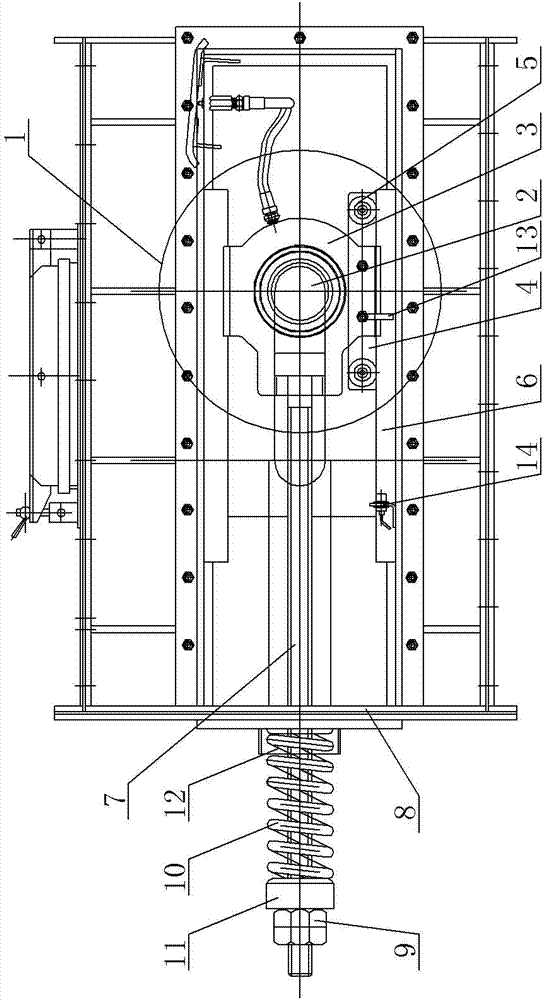
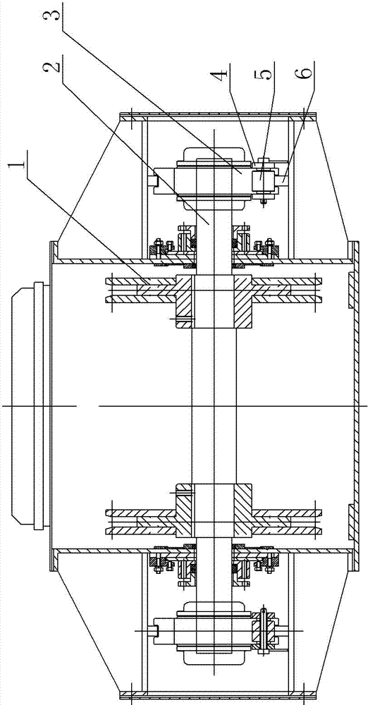
[0009] See Figure 1 ~ Figure 2 , which includes a conveying chain 1, the end of the conveying chain 1 is set on the rotating shaft 2, the two ends of the rotating shaft 2 are respectively supported on the bearing seat 3, and the two sides of the bottom of the bearing seat 3 are respectively fastened with a mounting plate 4, and the two ends of the mounting plate 4 The middle position is provided with rollers 5 respectively, and the rollers 5 are supported on the limit guide rail 6 at the bottom, and the upper part of the bearing seat 3 is fastened to one end of the adjusting screw 7, and the other end of the adjusting screw 7 runs through the support vertical plate 8 and is fitted with a Nut 9, an automatic spring 10 is arranged between the nut 9 and the outer side of the bracket vertical plate 8, the automatic spring 10 is set on the adjusting screw rod 7, the inner side of the nut 9 is equipped with a guide washer 11, and the outer side of the bracket vertical plate 8 is pro...


PUM


Abstract

The invention provides a rolling tensioning structure for a chain conveyer. The rolling tensioning structure for the chain conveyer changes sliding friction in the tensioning process into rolling friction, reduces the acting force in the adjustment process, avoids fault tensioning of the chain conveyer under poor working conditions, meets the use requirements of equipment, reduces fault rate, and lowers maintenance cost. The rolling tensioning structure for the chain conveyer comprises a conveying chain, wherein the tail end of the conveying chain is installed on a rotary shaft in a sleeved mode, and the two ends of the rotary shaft are supported on a bearing seat respectively. The rolling tensioning structure for the chain conveyer is characterized in that two sides of the bottom of the bearing seat are respectively provided with an installation plate in a fastening mode, idler wheels are arranged in the middle positions of the two ends of each installation plate respectively, the idler wheels are supported on a limiting guide rail at the bottom, the upper portion of the bearing seat is connected with one end of an adjustment screw rod in a fastening mode, the other end of the adjustment screw rod penetrates through a support vertical plate and then is provided with a nut in a sleeved mode, an automatic spring is arranged between the nut and the outer lateral surface of the support vertical plate and installed on the adjustment screw rod in a sleeved mode, and a limiting protruding block is arranged at the bottom of the bearing seat in a downward protruding mode.

Description

technical field [0001] The invention relates to the structural technical field of chain conveyors, in particular to a rolling tensioning mechanism for chain conveyors. Background technique [0002] Chain conveyors are widely used in metallurgy, electric power, chemical industry and other industries to transport raw materials, dust collection and transportation, batching, etc. During the operation of the equipment, the conveyor chain will be extended due to wear, special working conditions, and self-stretching. Conveyors use bearing housings or sealing plates to make up for the extension through the screw rod and play the role of chain tension. However, this tensioning mechanism will be stuck and cannot be tensioned when the equipment is used for high temperature and long-distance transportation, so that the equipment cannot work normally because the chain is too loose and the phenomenon of chain breakage occurs. Contents of the invention [0003] In view of the existing a...

Claims


Application Information

Patent Timeline
Patent Type & Authority Applications(China)
IPC IPC(8): B65G23/44
Inventor 宋红梅杜道鉴
Owner WUXI XUELANG ENVIRONMENTAL TECH CO LTD
Learn More