
Pneumatic high-low creel

A creel and frame technology, applied in the field of pneumatic high and low creels, can solve the problems of user inconvenience, inconvenient replacement, high installation requirements, etc., and achieve the effect of convenient disassembly, simple installation, and economical convenience

Active Publication Date: 2014-03-05
YICHANG JINGWEI TEXTILE MACHINERY
View PDF6 Cites 1 Cited by
  • Summary
  • Abstract
  • Description
  • Claims
  • Application Information

AI Technical Summary

Problems solved by technology

The existing four-bar linkage mechanism adopted by this high and low creel is a parallelogram four-bar linkage mechanism with equal opposite sides. Its obvious disadvantage is that the high position of the creel is relatively low and the low position is relatively high, which is difficult for yarn changers. The operation is inconvenient
The lower position of the creel creates potential safety hazards for tall yarn changers; while the higher position of the creel creates obvious operational difficulties for short yarn changers
In addition, the gas spring used in this case has higher installation requirements, and its service life is shorter than that of ordinary springs. If the gas spring fails due to air leakage and other reasons, the gas spring will not be able to play a supporting role and can only be replaced with a new one. However, due to installation requirements High, it is inconvenient to replace, and the cost of the air spring is relatively high, so using this air spring will bring inconvenience to the user

Method used


Image

  • Pneumatic high-low creel
  • Pneumatic high-low creel
  • Pneumatic high-low creel

Examples


Embodiment Construction

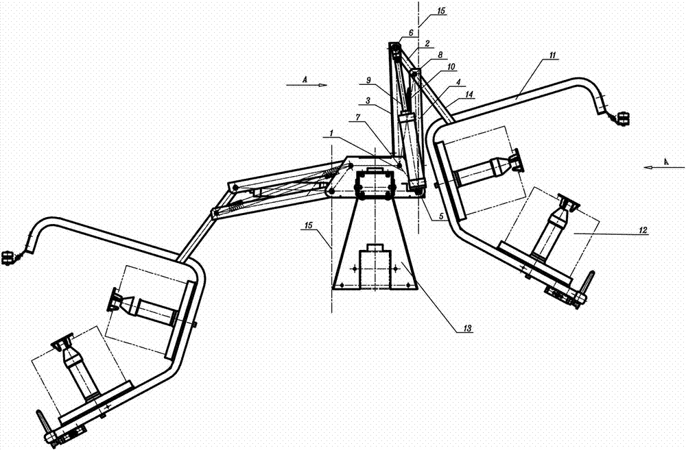
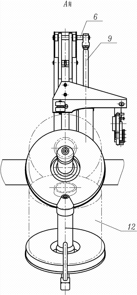
[0021] Such as Figure 1~3 Among them, a pneumatic high and low creel includes a frame 13, and the package frame 11 is supported on the frame 13 through a four-bar linkage mechanism to switch between the yarn loading position and the working position;

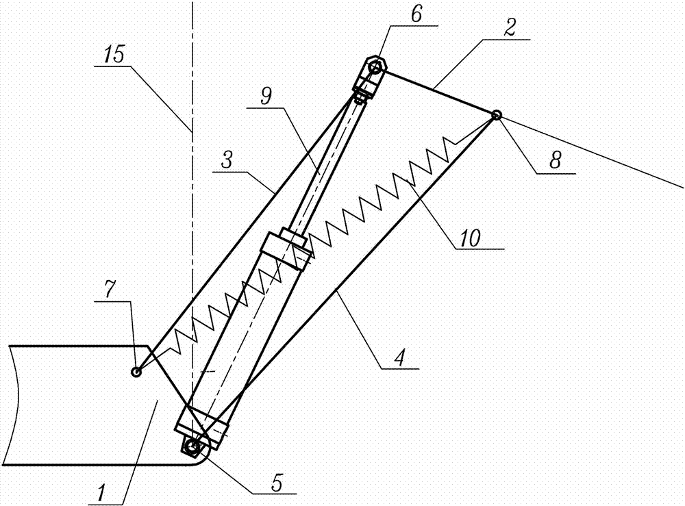
[0022] The structure of the four-bar linkage is:

[0023] The third link 3 is hinged with the upper fixed hinge shaft 7 fixed on the frame 13, the fourth link 4 is hinged with the lower fixed hinge shaft 5 fixed on the frame 13, and the second link 2 is hinged through the upper movable hinge shaft 6 is hinged with the third link 3, the second link 2 is hinged with the fourth link 4 through the lower movable hinge shaft 8, and the first link 1 is formed between the upper fixed hinge shaft 7 and the lower fixed hinge shaft 5;

[0024] The cylinder block adopts the cylinder 9 with air intake at both ends. One end of the cylinder 9 is hinged with the lower fixed hinge shaft 5, and the other end is hinged with the upper movable hinge shaf...


PUM


Abstract

A pneumatic high-low creel comprises a machine frame, and a coiling frame is supported on the machine frame through a four-connecting-rod mechanism, so that the coiling frame can be switched between a yarn feeding position and a work position. One end of an air cylinder is hinged to a lower fixed hinging shaft, air enters from the two ends of the air cylinder, the other end of the air cylinder is hinged to an upper movable hinging shaft, and when the pneumatic high-low creel is in the yarn feeding position and the work position, the air cylinder inclines at two sides of the vertical line passing the lower fixed hinging shaft respectively. The pneumatic high-low creel is further provided with a tension spring, and the tension spring is arranged between the upper fixed hinging shaft and the lower movable hinging shaft. Through the air cylinder, the sustaining force of the air cylinder can be lowered when the pneumatic high-low creel is in the work position. According to the optimized scheme, by being matched with the added tension spring, the tensioning force of the tension spring can be lowered. In addition, it is well known that the tension spring is convenient to mount and dismount, and is lower in cost and longer in service life compared with a pressure spring, and usually the tension spring does not thoroughly break down as the pressure spring. The pneumatic high-low creel has the advantages of being easy to install, economical, convenient to use and friendly to users, and saves labor when operated.

Description

Technical field [0001] The invention relates to a high and low creel in the field of textile machinery, in particular to a pneumatic high and low creel for providing outer yarn feeding packages for twisting threads of a direct twister. Background technique [0002] The high and low creel of the existing direct twisting machine is located at the top of the machine, and the panel for storing the yarn creel can be high or low, which is the so-called high and low creel. An elastic support pad is attached to the panel to prevent the strands of the end face of the feeding yarn package from falling off. The high and low creel is equipped with a creel thread tensioner and a self-locking mechanism, which can be self-locked in the low position, so that the creel can be replaced with a package. For example, CN1453200A discloses the following scheme. There is a cylinder that can receive compressed air at both ends, and the two ends of the cylinder are respectively fixed on the two opposite ...

Claims


Application Information

Patent Timeline
IPC IPC(8): D01H1/18
Inventor 陆国兴杨华明张明许金甲张金鹏汪斌
Owner YICHANG JINGWEI TEXTILE MACHINERY
Learn More