
Small harmonic reducer and optimum design method thereof

A harmonic reducer, optimized design technology, applied in the direction of mechanical equipment, portable lifting devices, gear transmissions, etc. shifting and other issues to achieve the effects of saving development costs, optimizing design methods, and realizing processing and manufacturing

Active Publication Date: 2014-03-05
NO 771 INST OF NO 9 RES INST CHINA AEROSPACE SCI & TECH
View PDF4 Cites 19 Cited by
  • Summary
  • Abstract
  • Description
  • Claims
  • Application Information

AI Technical Summary

Problems solved by technology

[0002] The standard harmonic reducer has been widely used in the field of steering gear such as missiles, satellites, and unmanned aerial vehicles. The wall thickness of the flexspline of the standard harmonic reducer is σ=(0.01~0.0145)d, where d is the flexspline The diameter of the degree circle, the height of the meshing teeth is h=(1.4~1.6)m, where m is the gear module; however, the existing design method is applied to the design of small harmonic reducers with a diameter of less than 25mm and a torque greater than 5N m At the same time, the structural strength of the obtained small harmonic reducer is not enough, and the fatigue fracture of the flexspline, the wear of the tooth surface, the slippage of the gear or the wave generator are prone to occur, and the transmission torque is small, which cannot meet the actual use requirements.

Method used

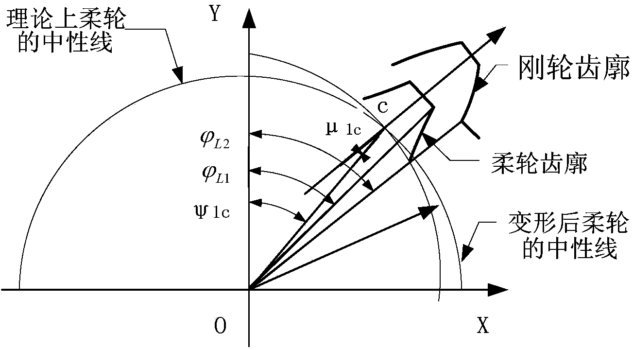
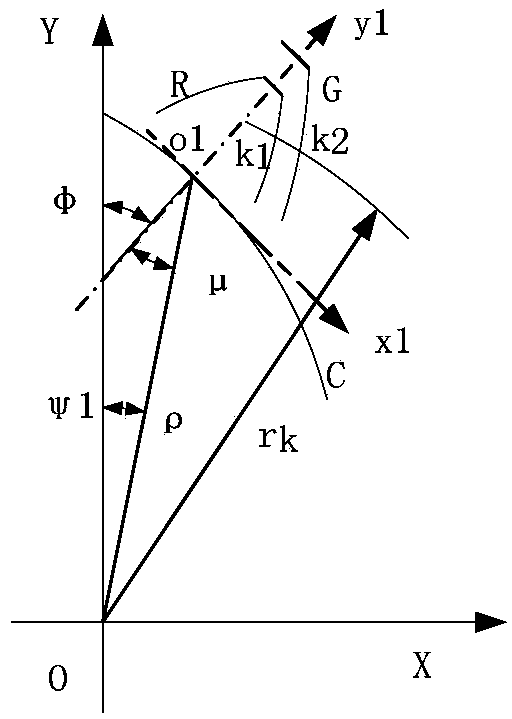
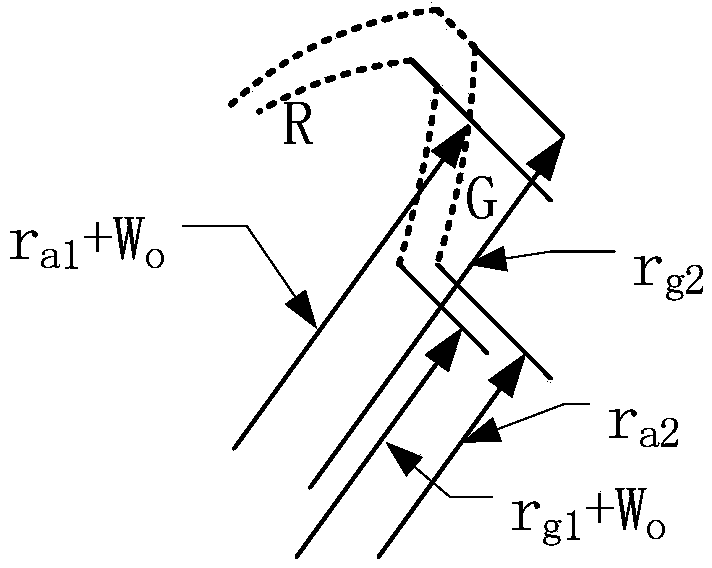

Image

  • Small harmonic reducer and optimum design method thereof
  • Small harmonic reducer and optimum design method thereof
  • Small harmonic reducer and optimum design method thereof

Examples


Embodiment Construction

[0043] The present invention will be further described in detail below in conjunction with specific embodiments, which are explanations of the present invention rather than limitations.

[0044] A method for optimal design of a small harmonic reducer according to the present invention comprises the following steps,

[0045] 1) Determine the calculation parameters required for the optimal design, and calculate the target parameters of the optimal design; the calculation parameters are the gear tooth height h n , flexspline wall thickness S and flexspline displacement coefficient x 1 , and according to the correction coefficient and the known design parameters, the following optimization formulas are used to calculate the value,

[0046] h n =(1.8~2)m;

[0047] S=((75+Z1 / 4)Z1×m) / 1000+ζ 1 ×m;

[0048] x 1 =1.25+S / m+ζ 2 ;

[0049] Among them, m is the gear module, Z 1 is the number of flex gear teeth, ζ 1 is the torque correction coefficient, ζ 2 is the modification coeff...


PUM


Abstract

The invention discloses an optimum design method of a small harmonic reducer. The optimum design method includes the steps 1), determining calculating parameters required by the optimum design to obtain target parameters of the optimum design; 2), determining a data range of the calculating parameters and the target parameters to obtain a target parameter solution set in accordance with the data range; 3), subjecting the target parameters in the target parameter solution set which is in accordance with the data range to iterative loop filtering to obtain optimal target parameters; 4), according to the obtained optimal target parameters and the corresponding calculating parameters, calculating to obtain other processing and manufacturing parameters to perform optimum design and manufacturing of the small harmonic reducer. The small harmonic reducer comprises a rigid gear and a flexible wheel which are mutually matched and adopts a wave generator of a double-wave-cam structure; the processing and manufacturing parameters are obtained by the above optimum design method. By means of adding correction factors and performing optimum design adjustment upon key parameters, the small harmonic reducer which is high in structural strength, long in service life and capable of realizing processing and manufacturing is obtained.

Description

technical field [0001] The invention relates to the structural design of a harmonic reducer, in particular to an optimal design method for a small harmonic reducer. Background technique [0002] The standard harmonic reducer has been widely used in the field of steering gear such as missiles, satellites, and unmanned aerial vehicles. The wall thickness of the flexspline of the standard harmonic reducer is σ=(0.01~0.0145)d, where d is the flexspline The diameter of the degree circle, the height of the meshing teeth is h=(1.4~1.6)m, where m is the gear module; however, the existing design method is applied to the design of small harmonic reducers with a diameter of less than 25mm and a torque greater than 5N m At this time, the structural strength of the obtained small harmonic reducer is not enough, and the fatigue fracture of the flexspline, the wear of the tooth surface, and the slippage of the gear or wave generator are prone to occur, and the transmission torque is small,...

Claims


Application Information

Patent Timeline
IPC IPC(8): F16H1/28F16H55/17F16H55/08
CPCF16H55/0833F16H55/17F16H2055/0866
Inventor 龚荣文李忠涛赵亚妮代永波
Owner NO 771 INST OF NO 9 RES INST CHINA AEROSPACE SCI & TECH
Learn More