Quick connector device

A joint device and fast technology, applied in the direction of fixing device, rod connection, connecting member, etc., can solve the problems of long connecting rod or wrench of clamping device, strict diameter requirements of clamped parts, and difficulty in manufacturing internal racks, etc. To achieve the effect of wide size requirements, wide size range, avoid damage to the hose and long operating time

Active Publication Date: 2017-01-18
DALIAN CONSERVATION SCI & TECH CO LTD
View PDF14 Cites 0 Cited by
  • Summary
  • Abstract
  • Description
  • Claims
  • Application Information

AI Technical Summary

Problems solved by technology

[0003] A quick clamping device disclosed in ZL201220481905.1 is suitable for a wide range of diameters, but it is only suitable for clamping round objects. It is difficult to manufacture the inner rack on it. If the tooth pitch is small, the strength will be low. When the clamped part is large and hard, it is likely to be difficult to clamp; at the same time, there is a problem that it is not easy to disassemble
[0004] Chinese invention patent application 201110376678.6 discloses a quick clamping Hafu block, ZL200520070064.4 discloses a quick clamping mechanism, ZL00232625.6 discloses a quick pipe clamp, etc.; all can achieve the purpose of quick clamping, but they are also It is only suitable for the clamping of round objects and has strict requirements on the outer diameter of the clamped parts; otherwise, there will be problems that are not easy to clamp
In addition, the aforementioned clamping devices all require long linkages or wrenches, making them often inoperable when used in tight spaces
[0005] In addition to the above-mentioned problems, the quick clamping device disclosed in ZL201320056193.3 and ZL201220050081.2 and the clamp for connecting soft and hard pipes disclosed in Chinese invention patent application 201210548479.3 are complicated in structure
[0006] It can be seen that there is a common problem in the prior art, that is, most of the existing clamping devices are only suitable for cylindrical objects to be clamped, and have strict requirements on the diameter of the clamped

Method used


Image

  • Quick connector device
  • Quick connector device
  • Quick connector device

Examples


Embodiment 1

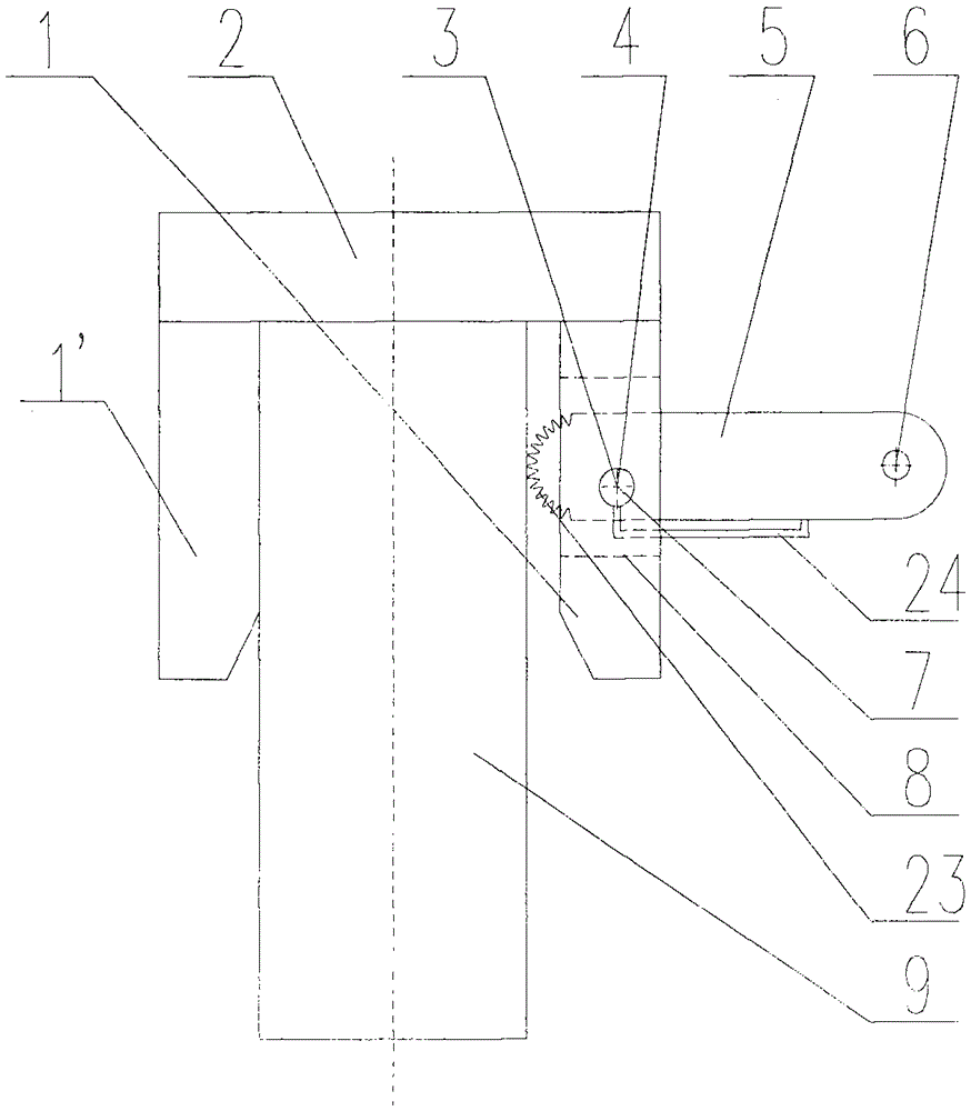
[0063] Example 1 The clamping jacket is an inverted U-shaped structure and a quick clamping release device with a clamping rod on one side

[0064] A quick clamping and releasing device, including an inverted U-shaped clamping jacket composed of two parallel vertical plates 1, 1' and a top plate 2 vertically fixed together above it, a clamping rod 5 and a clamping Tight bar 5 is connected together with clamping outer hinge shaft 3 of clamping outer cover, as figure 1 As shown; a vertical plate 1 of the inverted U-shaped groove clamping jacket is provided with a circular through hole 4, and the circular through hole 4 is parallel to the top plate 2 of the inverted U-shaped jacket and another vertical wall parallel to it. Plate 1'. A square or rectangular hole 8 is formed symmetrically or not completely symmetrically to the axis of the circular through hole 4 on the vertical plate 1 having the circular through hole 4 . One end on the clamping rod 5, that is, the clamping end, ...

Embodiment 2

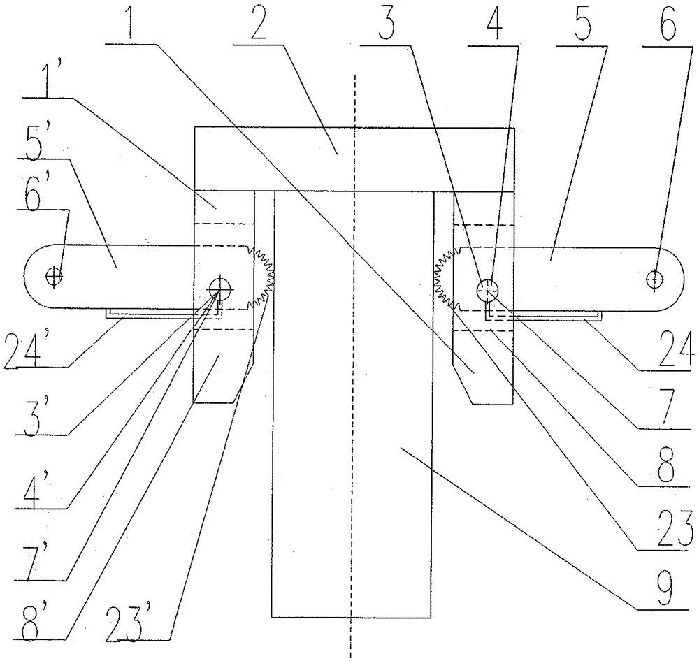
[0066] Example 2 The quick clamping and releasing device with the clamping jacket having an inverted U-shaped structure and clamping rods on both sides

[0067] Such as figure 2 As shown, in order to achieve clamping in a wider size range or to achieve the purpose of flexible operation, it is characterized in that the other vertical plate 1' is symmetrically opened with square or rectangular holes 8', and in this vertical plate 1' A circular through hole 4' is symmetrically opened on the top. Clamping rods 5' and hinge shafts 3' of the same size are installed symmetrically. A shaft hole 7' and a coupling hole 6' parallel to each other are respectively provided on the clamping end and the force application end of the clamping rod 5'. The simultaneous rotation of the two clamping rods 5 and 5' can allow a wider size range of the clamped object 9 under the condition of constant clamping force.

[0068] In order to enable the quick clamp release device to enter the clamped pie...

Embodiment 3

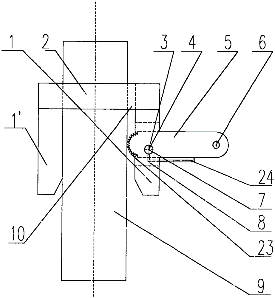
[0070] Embodiment 3 That is, on the basis of Embodiment 1, the quick clamping and releasing device with a hole in the top plate

[0071] Such as image 3 As shown, for cylindrical objects, due to the needs of some occasions, on the basis of the above-mentioned scheme, the top plate 2 of the clamping sleeve is opened at a position between the two vertical plates and perpendicular to the top plate 2. A circular hole 10 with a parallel spacing not smaller than the two vertical plates 1 and 1 ′, the circular hole 10 is a through hole coaxial with the clamping jacket.


PUM


Abstract

The invention relates to a quick clamping and releasing device and a quick connector device with the quick clamping and releasing device. The quick clamping and releasing device comprises a clamping device body, and the body comprises an outer clamping sleeve and more than one clamping rod. The outer clamping sleeve comprises a side wall, and the inner surface of the side wall is a work surface. The clamping rods are evenly and symmetrically distributed along the side wall of the outer clamping sleeve, and the clamping ends of the clamping rods penetrate through the side wall of the outer clamping sleeve and are hinged to the outer clamping sleeve on the side wall of the outer clamping sleeve. Connecting holes are formed in the force application ends of the clamping rods. The rotating track of the contact position of the clamping ends of the clamping rods and a piece to be clamped along a hinge shaft is an involute or an Archimedes helix. Objects of different shapes and sizes can be clamped fast, and the problem that a hoisted piece is hard to hoist due to the fact that a steel wire rope cannot penetrate through the hoisted piece is solved. The quick clamping and releasing device can be used as a light pipe quick connector device and a tool for pipeline pressure testing and climbing, the operation is convenient, the structure is simple, cost is low, the application range is wide, and the application condition is wide.

Description

technical field [0001] The invention relates to a clamping device and a quick joint device. Background technique [0002] Existing clamping devices are varied and of great variety, each having its own advantages and disadvantages. Such as: [0003] A quick clamping device disclosed in ZL201220481905.1 is suitable for a wide range of diameters, but it is only suitable for clamping round objects. It is difficult to manufacture the inner rack on it. If the tooth pitch is small, the strength will be low. When the clamped part is large and hard, it is likely to be difficult to clamp; at the same time, there is a problem that it is not easy to disassemble. [0004] Chinese invention patent application 201110376678.6 discloses a quick clamping Hafu block, ZL200520070064.4 discloses a quick clamping mechanism, ZL00232625.6 discloses a quick pipe clamp, etc.; all can achieve the purpose of quick clamping, but they are also It is only suitable for the clamping of round objects and ...

Claims


Application Information

Patent Timeline
Patent Type & Authority Patents(China)
IPC IPC(8): F16L37/08B66C1/42F16B1/02
CPCF16B1/02F16B7/0473
Inventor 梁有祥王嘉贤姜丰岷李果毅
Owner DALIAN CONSERVATION SCI & TECH CO LTD
Why Eureka
Try Eureka