
Annular self-locking type hydraulic leg

A hydraulic outrigger and self-locking technology, which is applied in the field of host support of the reel sprinkler irrigation machine, can solve the problems of increasing costs and achieve the effects of high reliability, simple structure and wide practicability

Inactive Publication Date: 2014-03-05
CHINA UNIV OF MINING & TECH
View PDF9 Cites 3 Cited by
  • Summary
  • Abstract
  • Description
  • Claims
  • Application Information

AI Technical Summary

Problems solved by technology

In order to ensure the accuracy and stability of the support, the hydraulic lock is required to have no internal leakage, thus increasing the cost of the equipment

Method used


Image

  • Annular self-locking type hydraulic leg

Examples


Embodiment Construction

[0010] An embodiment of the invention will be further described below in conjunction with the accompanying drawings:

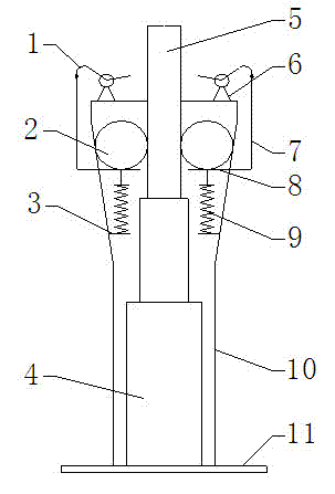
[0011] The annular self-locking hydraulic support leg of the present invention is mainly composed of a friction ring 2, a hydraulic cylinder 4, a friction inner column 5, a shift fork 8, a spring 9, an outer cylinder 10, and a base 11, and the outer cylinder 10 is arranged on the base 11 Above, the upper part of the outer cylinder 10 is trumpet-shaped, and the outer cylinder 10 is provided with a hydraulic cylinder 4 fixed on the base 11. The upper end of the piston rod of the hydraulic cylinder 4 is provided with a friction inner column 5 whose upper end extends out of the outer cylinder 10, and the friction inner A friction ring 2 is provided between the column 5 and the upper inner wall of the outer cylinder 10, and the friction ring 2 surrounds and is closely attached to the friction inner column 5. The middle part of the inner wall of the outer cylinder 10...


PUM


Abstract

An annular self-locking type hydraulic leg comprises a hydraulic cylinder, an outer barrel, an inner friction column, friction rings, springs and an unlocking mechanism. The hydraulic cylinder comprises a cylinder body and a piston rod, the upper end of the piston rod is fixedly connected with the lower end of the inner friction column, and the upper end of the inner friction column extends out of the outer barrel. The annular self-locking type hydraulic leg can complete supporting by only relying on mechanical self locking formed among the friction rings, the outer barrel and the inner friction column when the piston rod drives the inner friction column to extend out to the state needed by working, and the hydraulic cylinder no longer needs to bear support force, so that requirement on a hydraulic lock is lowered. When the annular self-locking type hydraulic leg completes supporting, the inner friction column can retract only by the aid of the unlocking mechanism. The annular self-locking type hydraulic leg is simple in structure, convenient to operate and high in reliability.

Description

technical field [0001] The invention relates to an annular self-locking hydraulic support leg, which is especially suitable for supporting the main machine of a reel type sprinkler irrigation machine, and also suitable for other occasions requiring support. Background technique [0002] With the development of industrialization and mechanization, outriggers are more and more used in industrial production and life. Hydraulic outriggers are widely used due to the advantages of flexible expansion and contraction, high reliability, and large load-bearing capacity. However, some occasions require hydraulic outriggers to support work for a long time. In order to ensure the accuracy and stability of the support, it is required that the hydraulic lock has no internal leakage, thus increasing the cost of the equipment. In order to solve this problem, it is necessary to propose a hydraulic outrigger with mechanical self-locking type, and complete the support in the form of mechanica...

Claims


Application Information

Patent Timeline
Patent Type & Authority Applications(China)
IPC IPC(8): F16M5/00
Inventor 吴波李伟朱真才卢昊沈刚
Owner CHINA UNIV OF MINING & TECH
Learn More