System and method for detecting damage of engineering machinery and tool thereof

A damage detection and cutting tool technology, which is applied in the direction of optical testing for flaws/defects, etc., can solve problems such as low detection efficiency, missed or false positives, and untimely problems, and achieve the effects of convenient operation, high detection efficiency, and accurate detection results

Inactive Publication Date: 2016-08-17
HUNAN SANY ROAD MACHINERY
View PDF5 Cites 0 Cited by
  • Summary
  • Abstract
  • Description
  • Claims
  • Application Information

AI Technical Summary

Problems solved by technology

[0006] In view of this, the present invention proposes a tool breakage detection system and method to solve the problems of untimely detection of tool breakage, low detection efficiency, and missed or false positives; the present invention also proposes an installation Construction machinery with the tool breakage detection system

Method used


Image

  • System and method for detecting damage of engineering machinery and tool thereof
  • System and method for detecting damage of engineering machinery and tool thereof
  • System and method for detecting damage of engineering machinery and tool thereof

Examples


Embodiment Construction

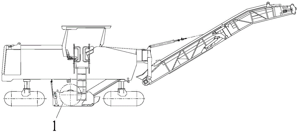
[0029] It should be noted that, in the case of no conflict, the embodiments of the present invention and the features in the embodiments can be combined with each other. The present invention will be described in detail below with reference to the accompanying drawings and embodiments. For the convenience of describing the specific solutions of the present invention, the tool damage detection system on a milling machine will be taken as an example to describe in detail below.

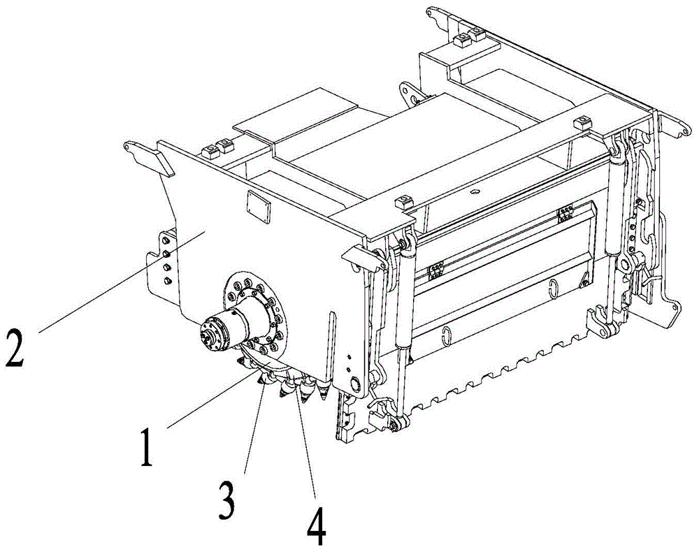
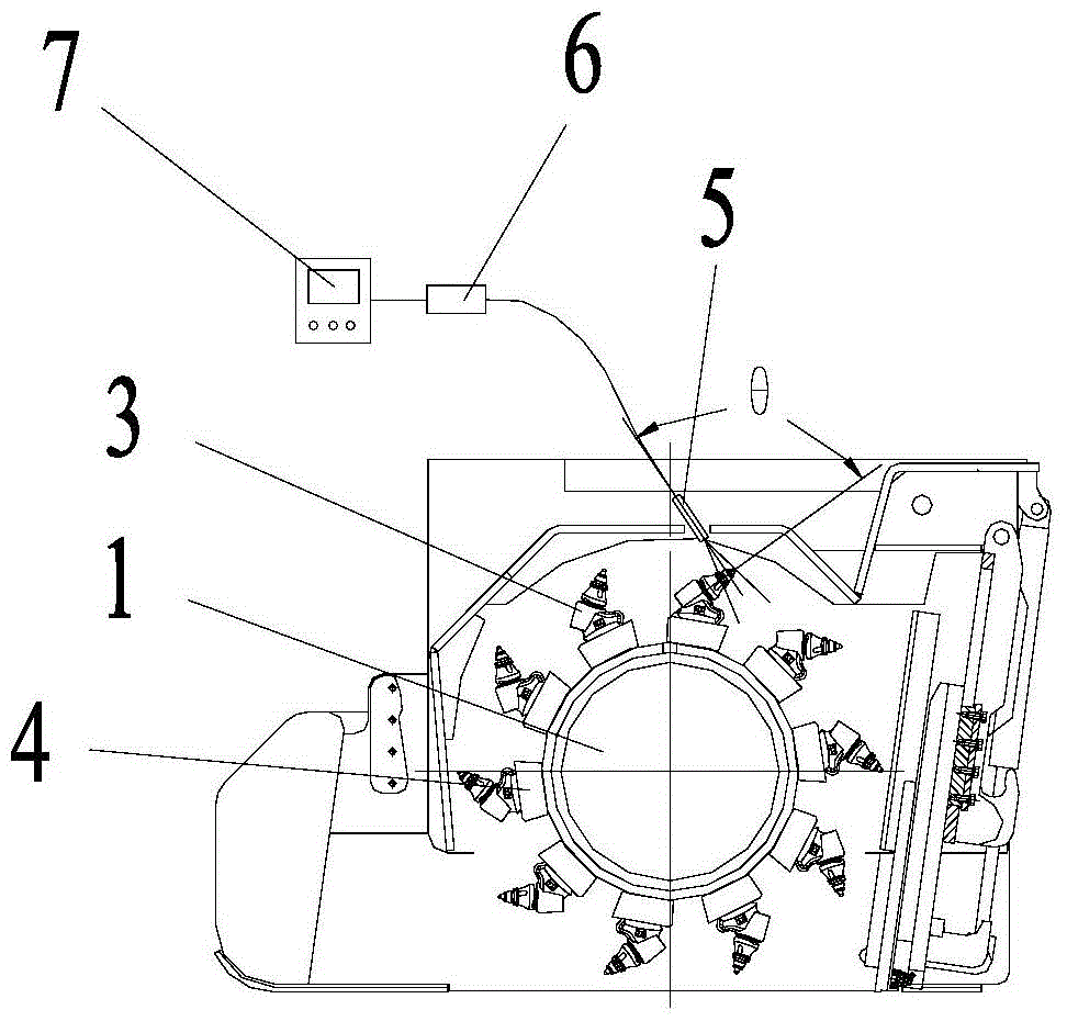
[0030] Such as Figure 1-3 As shown, the specific embodiment of the present invention provides a tool 3 damage detection system, including a working drum 1, a working casing 2, a tool 3 and a tool seat 4, the tool 3 is installed on the working drum 1 through the tool seat 4, and the working drum 1 is set inside the working cover 2, and the working cover 2 is also provided with an infrared video recording module 5 for recording the contour image information of the tool 3, and the infrared video recording...


PUM


Abstract

The invention discloses a tool breakage detection system, which includes a working drum, a working cover, a tool and a tool seat, the tool is installed on the working drum through the tool seat, and the working drum is arranged inside the working cover; the tool damage detection system also includes Infrared video recording module, data processing module and feedback terminal; the tool breakage detection system uses the tool in the working process, the temperature of the tool is significantly higher than the temperature of the surrounding environment, through the infrared video recording module installed on the work cover, records the temperature of the tool Shape, the shape information is processed by the data processing module, and finally fed back to the operator through the feedback terminal, so as to detect the damage of the tool. Therefore, during the detection process, the tool breakage detection system can find problems in time, and the detection efficiency is high. The contour image of the tool under high temperature is obtained by using infrared video recording, and the detection results are relatively accurate. The invention also discloses a tool damage detection method and a construction machine equipped with the tool damage detection system.

Description

technical field [0001] The invention specifically relates to a tool damage detection system and method, and the invention also relates to a construction machine equipped with the tool damage detection system. Background technique [0002] At present, for construction equipment (such as milling machines, recycling machines, surface mining machines, etc.) Knives (bullet-type or disc-type), use alloy tools to break the hard construction surface; due to long-term friction or impact between the alloy tool and the hard construction surface, the alloy tool is easily damaged, which further threatens the tool holder; for Avoiding damage to the tool block and working drum often requires frequent inspection of the tool for breakage. [0003] In order to ensure construction safety and avoid smoke and dust spillage, the working drum is usually installed inside the working casing. This structure makes it difficult to check the knives. It is necessary to stop frequently and open the worki...

Claims


Application Information

Patent Timeline
Patent Type & Authority Patents(China)
IPC IPC(8): G01N21/88
Inventor 刘川罗东志付秋刚
Owner HUNAN SANY ROAD MACHINERY
Why Eureka
Try Eureka