Rotating electromagnet

A technology of rotating electromagnets and yokes, applied in the field of electromagnets, can solve the problems of high coil power, poor economy, large volume and weight, etc., and achieve the effects of large output torque and simple structure

Inactive Publication Date: 2014-03-05
ZHENGZHOU AIRCRAFT EQUIP
View PDF4 Cites 4 Cited by
  • Summary
  • Abstract
  • Description
  • Claims
  • Application Information

AI Technical Summary

Problems solved by technology

[0002] At present, the characteristic of the existing rotating electromagnet is that after the coil is energized, the moving direction of the armature is perpendicular to the direction of the magnetic force line, and its economy is worse than that of the snap-fit ​​electromagnet, that is, when doing the same mechanical work, its volume and weight are lower than those of the snap-fit ​​electromagnet. It is larger than the snap-in electromagnet, and the power required by the coil is also large. In some cases where the load torque is large, it cannot meet the requirements.

Method used


Image

  • Rotating electromagnet
  • Rotating electromagnet

Examples


Embodiment Construction

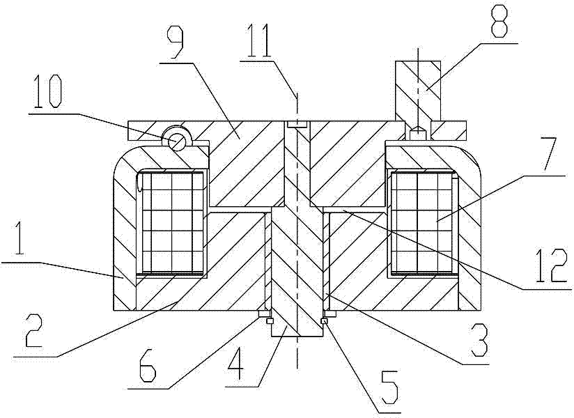
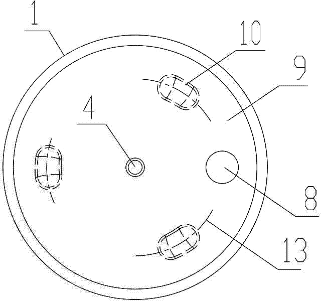
[0009] Such as figure 1 , 2 As shown, the rotary electromagnet of the present invention is composed of a yoke 1, an iron core 2, an armature 9, a coil 7, and a ball 10; the yoke 1 is an inverted U structure with a jack on the top surface, and the The top surface of the inverted U structure yoke 1 is uniformly provided with three upper opening arc-shaped grooves distributed along the circumferential direction. The cross-section of the upper opening arc-shaped groove is arc-shaped, and the center of the upper opening arc-shaped groove The line 13 has a helical structure relative to the longitudinal centerline 11, and the two ends of the arc-shaped groove on the upper opening are spherical surfaces tangent to the bottom surface of the groove; the iron core 2 is provided in the inverted U structure yoke 1 with a central hole The first stepped shaft, the diameter of the upper end of the first stepped shaft is smaller than the diameter of the lower end; the armature 9 is a second s...


PUM


Abstract

The invention discloses a rotating electromagnet which is composed of a magnetic yoke, an iron core, an armature, a coil and balls. The magnetic yoke is of an inverted-U structure with an inserting hole formed in the top surface, multiple upper opening arc-shaped grooves which are distributed circumferentially are uniformly formed in the top surface of the inverted-U-structure magnetic yoke, a central line of each upper opening arc-shaped groove is of a spiral line structure relatively to a longitudinal central line, the iron core is a first step shaft arranged in the inverted-U-structured magnetic yoke and provided with a central hole, the armature is a second step shaft with diameter of the upper end larger than that of the lower end, the small-diameter end of the second step shaft is mounted in the inserting hole of the magnetic yoke from a position above the inverted-U-structured magnetic yoke in an inserted manner, lower opening arc-shaped grooves are formed at positions, corresponding to the upper opening arc-shaped grooves, of a lower platform surface of the large-diameter end of the second step shaft, the balls are positioned in a raceway formed by the upper and lower opening arc-shaped grooves, and the coil is mounted on the first step shaft and the second step shaft of the inverted-U-structured magnetic yoke in a sleeve manner. The rotating electromagnet is larger in output torque than existing rotating electromagnets.

Description

technical field [0001] This invention relates to electromagnets, and more particularly to rotating electromagnets. Background technique [0002] At present, the characteristic of the existing rotating electromagnet is that after the coil is energized, the moving direction of the armature is perpendicular to the direction of the magnetic force line, and its economy is worse than that of the snap-fit ​​electromagnet, that is, when doing the same mechanical work, its volume and weight are lower than those of the snap-fit ​​electromagnet. It is larger than the snap-in electromagnet, and the power required by the coil is also large. In some cases where the load torque is large, it cannot meet the requirements. Contents of the invention [0003] The purpose of the present invention is to provide a rotating electromagnet with strong loading capacity. [0004] To achieve the above object, the present invention takes the following technical solutions: [0005] The rotary electrom...

Claims


Application Information

Patent Timeline
Patent Type & Authority Applications(China)
IPC IPC(8): H01F7/08
Inventor 张素萍韩文明刘生峰
Owner ZHENGZHOU AIRCRAFT EQUIP
Why Eureka
Try Eureka