Sectional-type energy consumption brake circuit of permanent-magnet direct current motor

A DC motor and energy-consuming braking technology, which is applied in the direction of the reduction device of the DC motor, the electric motor/converter plug, etc., can solve the problems of braking torque drop, large braking torque, high potential, etc., and achieve fast braking speed , large braking torque and good effect

Inactive Publication Date: 2014-03-05
LISHUI VOCATIONAL & TECHN COLLEGE
View PDF0 Cites 9 Cited by
  • Summary
  • Abstract
  • Description
  • Claims
  • Application Information

AI Technical Summary

Problems solved by technology

[0004] The biggest disadvantage of dynamic braking is that at the initial moment of braking, due to the high rotor speed, the generated potential is also high, and the braking torque is relatively large; as the motor speed decreases, the speed at which the armature coil cuts the magnetic field also decreases, and the

Method used


Image

  • Sectional-type energy consumption brake circuit of permanent-magnet direct current motor
  • Sectional-type energy consumption brake circuit of permanent-magnet direct current motor
  • Sectional-type energy consumption brake circuit of permanent-magnet direct current motor

Examples


Embodiment Construction

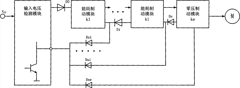
[0013] See attached figure 1 , the power supply is first sent to the voltage detection module, and the detection module detects two states of power on and power off. When the power is on, the control terminal outputs a low-level signal to lock all the braking modules behind, and the power passes through the diode D 0 Connect with the power supply terminal of the braking module in series at the back and finally supply power to the motor. At this time, all the braking modules are inactive and the motor is in normal working state.

[0014] When the power is turned off or the voltage drops to the motor stop voltage, the input detection module detects zero voltage or undervoltage status and confirms that the motor needs to stop, the control terminal of the input module turns to high level, canceling the locking of the following circuit, and the control The dynamic module starts to work.

[0015] The first energy consumption braking module starts to operate, the internal power tra...


PUM


Abstract

The invention provides a permanent-magnet direct current motor brake device completely achieving brake through electrical actions and having the advantages of being large in braking torque, high in brake speed, good in effect, fast in reaction, good in reliability and high in safety factor. The device is composed of a voltage detection module, i energy consumption braking modules and a zero-voltage braking module. When a zero voltage or under voltage is detected by an input detection module, the first energy consumption braking module works, a power transistor is saturated and switched on, an energy consumption resistor is connected to the two ends of the motor, inertia mechanical energy of a rotor is converted to electric energy, the electric energy is transmitted to the energy consumption resistor to be consumed through heating, and accordingly the motor can operate under braking. Voltage continuously decreases as the braking time of the motor increases. The first module is not in a saturation state any more because the voltage is too low, a high level is output by a control terminal, the next-level energy consumption braking module starts to work, and the first energy consumption braking process is repeated until the last module works.

Description

technical field [0001] The invention relates to an electronic circuit applied to braking control of a permanent magnet direct current motor, in particular to an energy consumption braking circuit applied to a permanent magnet direct current motor. Background technique [0002] In many working situations, the motor needs to be stopped quickly and accurately, which requires braking measures for the high-speed running motor. Common braking methods for electric motors include mechanical braking, electrical braking, etc. Among electrical braking, there are various forms such as reverse connection braking, energy consumption braking, and regenerative feedback braking. Among them, the mechanical braking method has disadvantages such as high cost, large volume, and heavy maintenance workload, especially the serious heat generation is not suitable for frequent braking and long-term braking; the current of the electrical reverse braking process is too large, and the end of braking is ...

Claims


Application Information

Patent Timeline
IPC IPC(8): H02P3/12
Inventor 赵洪徐爱亲
Owner LISHUI VOCATIONAL & TECHN COLLEGE
Why Eureka
Try Eureka