Stamping method

A technology of stamping forming and stamping device, which is applied in the field of stamping and forming method of raw materials, can solve the problems of material fracture forming, insufficient material inflow, defectiveness, etc.

Inactive Publication Date: 2016-01-20
NIPPON STEEL CORP
View PDF8 Cites 1 Cited by
  • Summary
  • Abstract
  • Description
  • Claims
  • Application Information

AI Technical Summary

Problems solved by technology

In such a molding method, there is insufficient inflow of the material from the cup-shaped intermediate material to the space between the punch and the cylindrical inner surface of the die, and molding defects such as material breakage at the corner of the tip of the punch are likely to occur. such problem

Method used


Image

  • Stamping method
  • Stamping method
  • Stamping method

Examples


Embodiment 1)

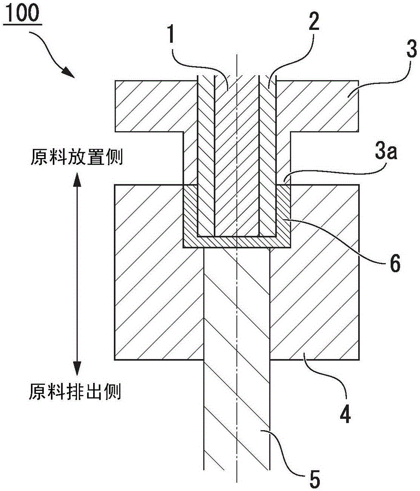
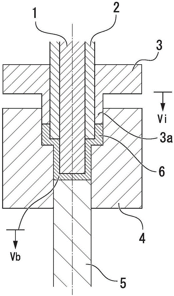
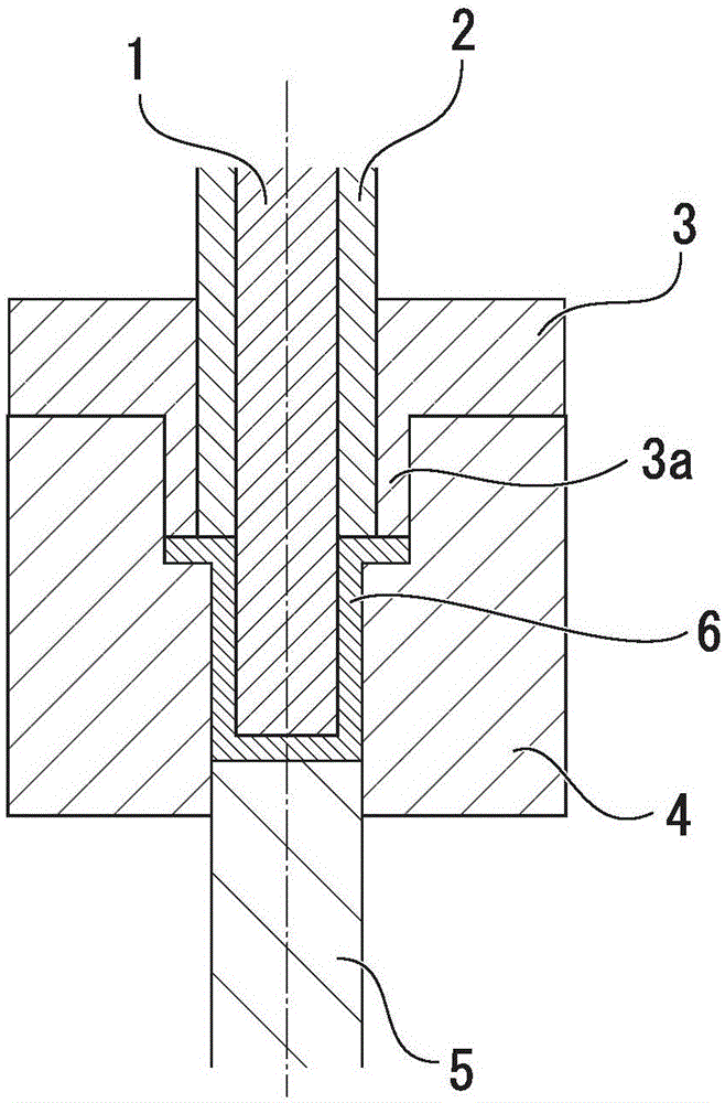
[0056] use Figure 1A ~ Figure 1C In the shown multi-axis press device, a carbon steel cup-shaped raw material with an outer diameter of φ90mm×wall thickness 2mm×height 30mm is formed into a cup with an outer diameter of φ50mm at room temperature while maintaining a wall thickness of 2mm. In this molding, the multi-axis punching device is set so that before and after (before and after filling) the raw material confirmed by preliminary molding is filled toward the inside of the mold, in any case the lowering of the outer peripheral punch 3 The ratio Vb / Vi of the velocity Vi to the descending velocity Vb of the punch has the same value. Table 1 shows the relationship between the speed ratio Vb / Vi in this molding and the molding result.

[0057] When the speed ratio Vb / Vi is in the range of 0.7 to 1.5, the molding is completed without breaking and burring the raw material. On the other hand, when the speed ratio Vb / Vi is less than 0.7, burrs which become a problem in product ma...

Embodiment 2)

[0061] use Figure 1A ~ Figure 1CThe shown multi-axis punching device molds an aluminum cup-shaped raw material with an outer diameter of φ120mm×wall thickness of 5mm×height of 40mm into a cup with an outer diameter of φ70mm at room temperature while maintaining a wall thickness of 5mm. In this molding, the multi-axis press device is set so that the ratio of the descending speed Vi of the outer peripheral punch 3 to the descending speed Vb of the punch before and after filling the mold with the raw material confirmed by preliminary molding is Vb / Vi are different values. Table 2 shows the relationship between the speed ratio Vb / Vi of the multi-axis press device and the molding results during the molding.

[0062] When the speed ratio Vb / Vi is in the range of 0.7 to 1.5 both before and after filling, molding is completed without causing breakage and burrs in the raw material. On the other hand, when the speed ratio Vb / Vi is a value smaller than 0.7 both before and after fillin...

Embodiment 3)

[0066] Further, use Figure 1A ~ Figure 1C The shown multi-axis punching device molds a carbon steel cup-shaped raw material with an outer diameter of φ80mm×wall thickness of 5mm×height of 45mm into a cup with an outer diameter of φ45mm at room temperature while maintaining a wall thickness of 5mm. Table 3 shows the relationship between the sum s of the gaps between the raw material 6 , the female mold 4 , and the anti-wrinkle device 2 during the molding, and the molding results.

[0067] [table 3]

[0068]

[0069] The gaps in Table 3 are in the Figure 3A The value obtained by dividing the sum s of gaps (gap in the horizontal direction) formed between the raw material 6 , the female mold 4 and the anti-wrinkle device 2 in the illustrated state by the plate thickness dimension t of the raw material 6 .

[0070] When the velocity ratio Vb / Vi was in the range of 0.7 to 1.5 before and after filling, molding was completed without causing breakage and burrs in the raw materia...


PUM


Abstract

A press-forming method in which a multi-shaft press device that actuates a plurality of shafts independently is employed to draw the bottom of a recess formed in a base material by pressing out the bottom of the recess into a hollow shaft. The press-forming method is provided with a first step in which the base material is set in a concave mold; and a second step in which a first tool presses the end face of a side wall, which defines the recess in the base material and forms a cylindrical shape, in the axial direction of the first tool at a first speed (Vi), while a second tool simultaneously molds the bottom of the base material by pressing out the bottom of the base material in the axial direction of the second tool at a second speed (Vb). At the second step, the ratio (Vb/Vi) of the second speed (Vb) to the first speed (Vi) is controlled to be within the range of 0.7 to 1.5.

Description

technical field [0001] The invention relates to a stamping forming method of raw materials. [0002] This application claims priority based on Japanese Patent Application No. 2011-145903 for which it applied in Japan on June 30, 2011, and uses the content here. Background technique [0003] As a method of molding a cylindrical container with a bottom and a constant diameter, and a multi-step cylindrical product having a step part with a different diameter in the middle, the method of further drawing a cup-shaped intermediate material is widely used. method. For example, Non-Patent Document 1 discloses a redrawing method in which an intermediate material formed from a disk-shaped material into a cup shape in a first step is drawn again in a second step. [0004] In this processing method, the cup-shaped intermediate material formed in the first step is sandwiched between a cylindrical tool inserted into its inner surface, that is, a wrinkle-preventing device, and a female d...

Claims


Application Information

Patent Timeline
Patent Type & Authority Patents(China)
IPC IPC(8): B21D22/28B21D24/00B21D24/04
CPCB21D22/28B21D24/04
Inventor 和田康裕山本修治
Owner NIPPON STEEL CORP
Why Eureka
Try Eureka