

Aluminum pipe bagging device
A bagging device and aluminum tube technology, which is applied to the field of aluminum tube bagging devices, can solve the problems of time-consuming and laborious, unsuitable for large-scale industrial production, and labor costs soaring, so as to reduce labor intensity, improve bagging efficiency and improve efficiency. Economic benefit and manpower saving effect
- Summary
- Abstract
- Description
- Claims
- Application Information
AI Technical Summary
Problems solved by technology
Method used
Image

Examples
Embodiment
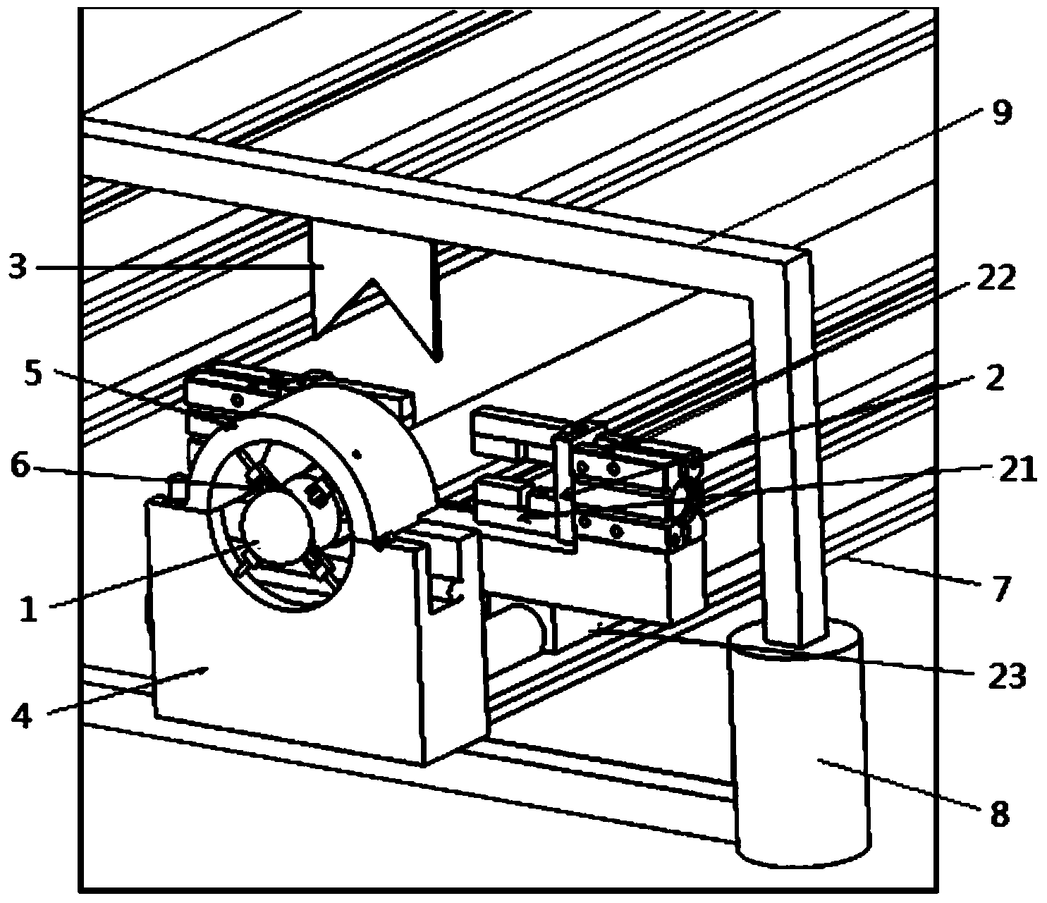
[0018] Embodiment: An aluminum tube bagging device, the front end of the aluminum tube is provided with a guide jig 1 that can stretch the bag, and the rear of the guide jig is provided with a clamp that can clamp the head end of the bag and move along the length direction of the aluminum tube The jig 2 is provided with a cutting knife 3 capable of cutting off the bag above the front end of the aluminum tube.
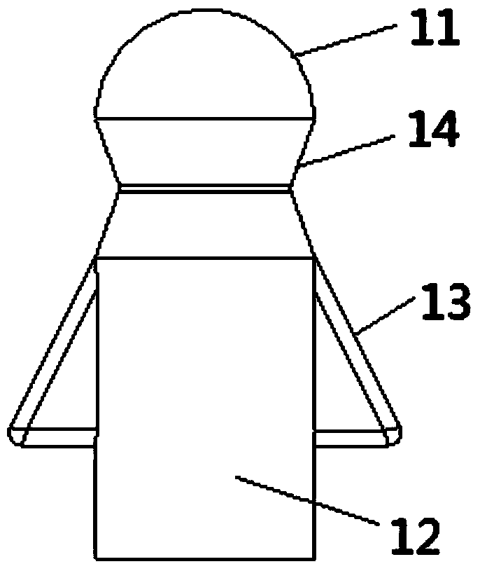
[0019] The guiding jig has a bag sleeve joint 11 and an aluminum tube socket 12, the aluminum tube socket is hollow columnar, the aluminum tube socket is sleeved on the front end of the aluminum tube, and the aluminum tube is socketed The front part of the part is provided with a number of expansion arms 13, and the expansion arms are equally distributed along the radial direction of the socket part of the aluminum tube, and each expansion wall has a radially outward opening from the front to the rear. Open the department.
[0020] The front end of the bag sleeve joint...
PUM
 Abstract
Description
Claims
Application Information