Automatic pipe feeding mechanism of filling production line

A technology of production line and upper tube, applied in packaging and other directions, can solve problems such as production line impact, achieve the effect of reducing equipment cost, improving operation stability and work efficiency, and stabilizing structure

Active Publication Date: 2014-03-12
LMZ YANGZHOU HOTEL SUPPLIES
View PDF5 Cites 6 Cited by
  • Summary
  • Abstract
  • Description
  • Claims
  • Application Information

AI Technical Summary

Problems solved by technology

[0004] Yet people find that after the above-mentioned "upper management mechanism" has been used for a long time or when the automatic program has an error due to an accident, there are often multiple "bottle bodies" that slide out after the "bottle divider baffle" is opened once, and fall into the "bottle body". Turning over the bottle pallet" has brought a great impact on the entire production line

Method used


Image

  • Automatic pipe feeding mechanism of filling production line
  • Automatic pipe feeding mechanism of filling production line
  • Automatic pipe feeding mechanism of filling production line

Examples


Embodiment 1

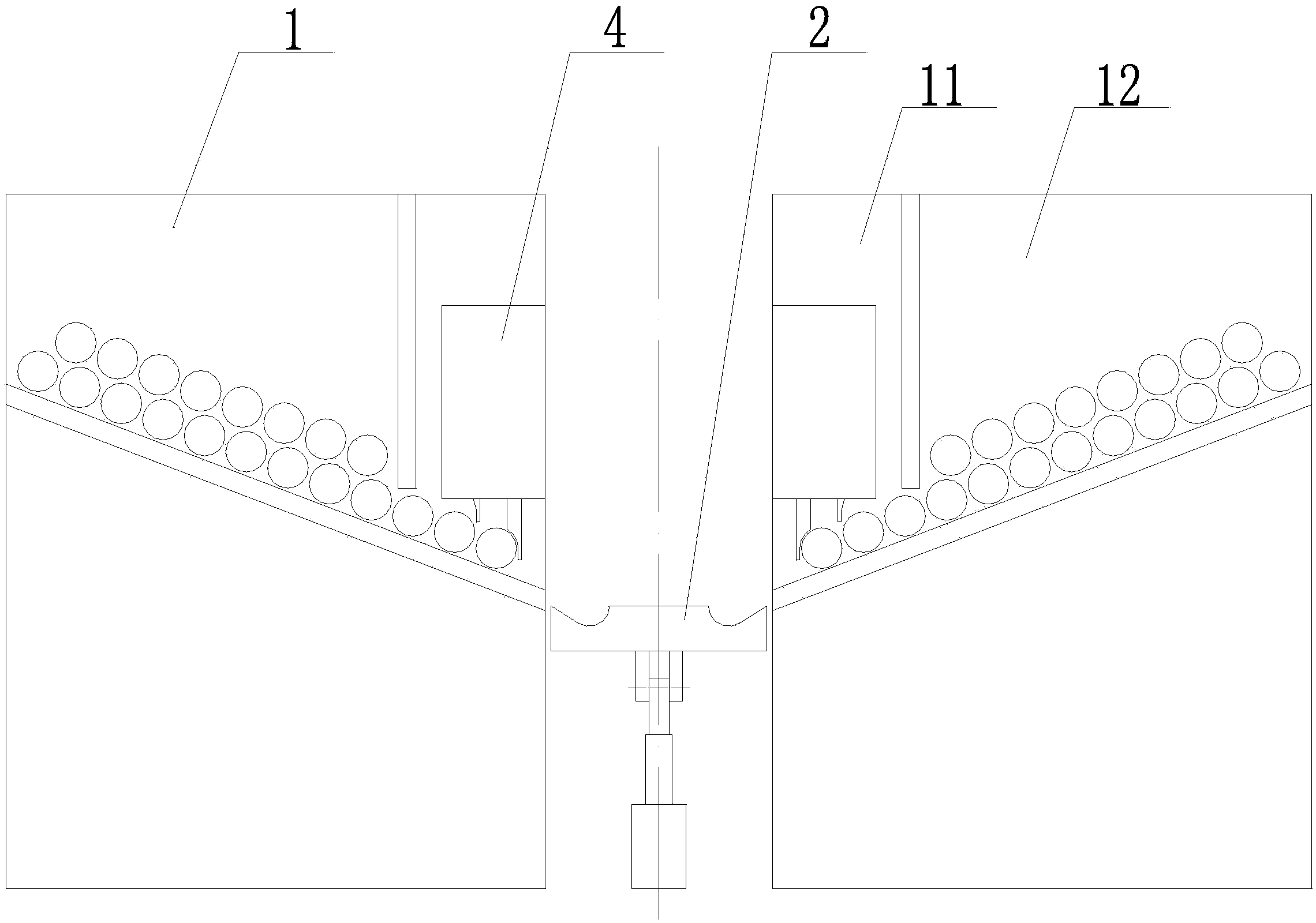
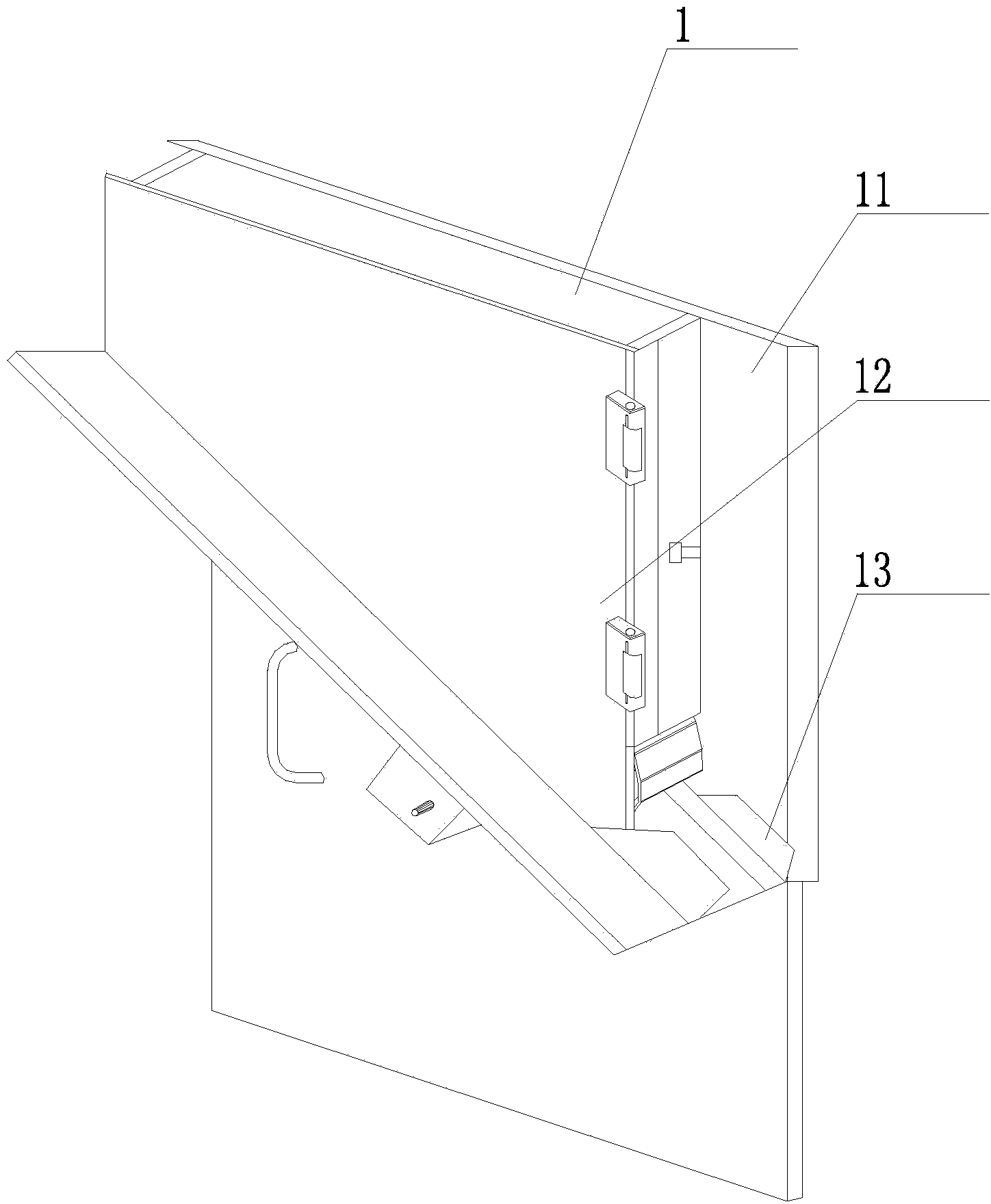
[0040] Example as figure 1 with 5 -7 shows: the quantitative lower tube switch 4 includes a hollow box 41, a vertical baffle 42-1, a vertical baffle 2 43-1, a movable lever 44-1 and a vertical driving device 45-1;

[0041] The first vertical baffle 42-1 is located between the second vertical baffle 43-1 and the flap 2, and the bottom plate of the box body 41 is provided with a The first vertical passage and the second vertical passage adapted to the second vertical baffle 43-1; the upper part of the first vertical baffle 42-1 is provided with a pin one 420-1, and the upper part of the second vertical baffle 43-1 With pin two 430-1;

[0042] The center of the movable lever 44-1 is located between the vertical baffle one 42-1 and the vertical baffle two 43-1, and is hinged on the inner wall of the box body 41, and the movable lever 44-1 A keyway-shaped through hole 1 441-1 for accommodating pin 1 420-1 and a keyway-shaped through hole 2 442-1 for accommodating pin 2 430-1 ar...

Embodiment 2

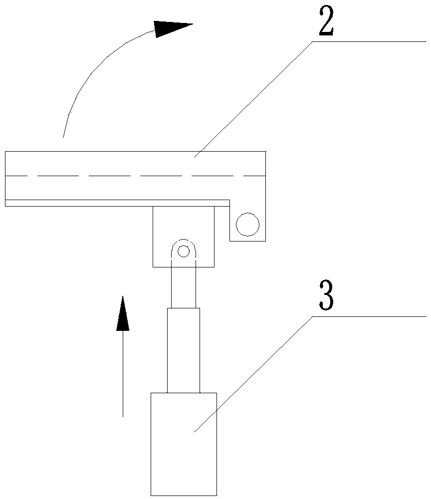
[0049] Example two such as figure 1 with 8 -12 shows: the quantitative lower tube switch 4 includes a box body 41 with an open bottom, a movable baffle 42-2, a movable baffle 2 43-2, a power disc 45-2, a rotary drive device and several pairs of horizontal Screw rod 44-2; a pair of horizontal screw rods 44-2 are located on the same vertical plane;

[0050] The movable baffle 1 42-2 is located between the movable baffle 2 43-2 and the flap 2, and the movable baffle 1 42-2 is provided with a plurality of sockets socketed on the horizontal screw 44-2. A strip-shaped vertical hole 421-2, the two sides of the vertical hole 421-2 are respectively provided with a number of nuts 423-2 socketed on the horizontal screw rod 44-2; the movable baffle plate 2 43 -2 is provided with a number of elongated vertical holes 431-2 which are socketed on the horizontal screw rod 44-2. Nut II on 433-2;

[0051] The first movable baffle 42-2 is provided with a friction strip 1 422-2 on the end sur...


PUM


Abstract

The invention discloses an automatic pipe feeding mechanism of a filling production line which has the advantages that the structure is ingenious, the application method is simple and practicable, the application range is wide; when toothpaste pipe (or other flexible pipes) leave a bin, only single toothpaste pipe (or other flexible pipes) falls in turning plates each time the automatic pipe feeding mechanism is opened. The automatic pipe feeding mechanism comprises the turning plate, a turnover device and a pair of pipe storing devices, wherein each pipe storing device comprises a vertical plate, a storing bin and a pipe charging groove; the storing bins are connected to the surfaces of the vertical plates fixedly, a pipe charging opening is formed in the bottom of the side (close to the turning plate) of each storing bin, and the bottom surfaces of the pair of storing bins are arranged in an inclined manner and both downwards point to the turning plate; quantitative pipe charging switches which are connected to the surfaces of the vertical plates are arranged above the pipe charging grooves. The automatic pipe feeding mechanism provided by the invention has the advantages that the single toothpaste pipe only falls in the turning plates each time of pipe charging by virtue of the quantitative pipe charging switches, a situation that a starting working procedure on the production line can generate an error is avoided, the operation stability and work efficiency of the whole production line are greatly improved, the structure is stable, the using effect is good, and the application range is wide.

Description

technical field [0001] The invention relates to the field of filling, in particular to the improvement of the structure of the automatic tube loading mechanism therein. Background technique [0002] The filling and packaging of toothpaste tubes are similar to the tube packaging used for cream and emulsion materials in the daily chemical, pharmaceutical and food industries. Among them, there is a representative document such as "A Fully Automatic High-Speed ​​Tube Filling and Sealing Machine" announced by the National Bureau on November 21, 2012, with the application number "2012200767738.2". Processing flow such as Figure 4 Shown: First put the tube on station A (toothpaste tube or other hoses are turned upright), then go to station B for calibration, then go to station C to find the mark, and go to station D for filling, and then sequentially After the E, F, and G stations, the first end sealing, the second end sealing and the tail cutting are carried out, and finally the...

Claims


Application Information

Patent Timeline
Patent Type & Authority Applications(China)
IPC IPC(8): B65B43/44
Inventor 兰进
Owner LMZ YANGZHOU HOTEL SUPPLIES
Why Eureka
Try Eureka