Hot galvanizing device and hot galvanizing method applicable to same
A technology of hot-dip galvanizing and heating chamber, applied in hot-dip galvanizing process, coating, metal material coating process, etc., can solve the problem of thick zinc layer thickness, reduce the thickness of zinc layer, increase fluidity, reduce effect of cooling
- Summary
- Abstract
- Description
- Claims
- Application Information
AI Technical Summary
Problems solved by technology
Method used
Image

Examples
Embodiment 1
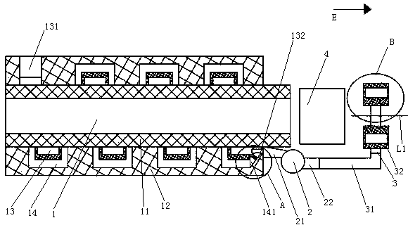
[0023] Embodiment one, see figure 1 , a hot-dip galvanizing device, including a heating furnace 1, a fan 2, an air knife 3 and a zinc pot 4.
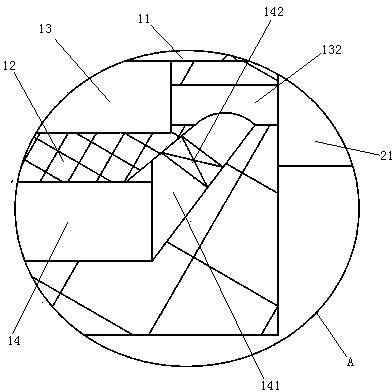
[0024] A shield 12 is provided on the furnace wall 11 of the heating furnace. A heating chamber 13 is formed between the shield 12 and the furnace wall 11 of the heating furnace. The heating chamber 13 is a channel structure extending spirally along the circumference of the heating furnace 1 . The heating chamber 13 is provided with a heating chamber air inlet 131 and a heating chamber air outlet 132 . The heating chamber air inlet 131 and the heating chamber air outlet 132 are located at both ends of the heating chamber 13 in the longitudinal direction. The shield 12 is provided with a thermal insulation chamber 14 . The heat insulation chamber 14 is a channel structure extending spirally along the circumference of the heating furnace 1 . The heat insulation chamber 14 is located on the side of the heating chamber 13 away from the...
Embodiment 2
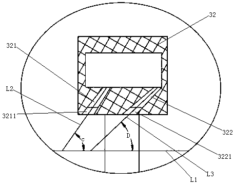
[0031] Embodiment two, see Figure 4 The difference from the first embodiment is that the sealing method between the heating chamber air outlet and the fan inlet is different. The specific sealing method is: the heating chamber air outlet 132 is provided with a flange 15 protruding from the surface of the shield 12 . The fan air inlet 21 is provided with an outer flange 23 . A sealing pipe 5 is provided between the air outlet 132 of the heating chamber and the air inlet 21 of the fan.
[0032] The sealing tube 5 includes a base 51 , an annular connecting groove 52 , a first sealing lip 53 and a second sealing lip 54 disposed on the base 51 . Both the base portion 51 and the connection groove 52 are compact bodies made of rubber material. A shroud sealing lip 55 is provided on the end surface of the outer side wall 521 of the connection groove. The shield sealing lip 55 is a sponge made of sponge material. A support bar 56 is disposed on a peripheral surface of the outer wa...
Embodiment 3
[0034] Embodiment three, see Figure 6 , the difference from the second embodiment is that the sealing lip of the shield part is not provided, but the flange 15 is directly sealed and fixed on the support bar 56 and the crimping fin 57 to realize the connection between the groove and the air outlet of the heating chamber 132 seals.
PUM
 Abstract
Description
Claims
Application Information
 - R&D
- Intellectual Property
- Life Sciences
- Materials
- Tech Scout
- Unparalleled Data Quality
- Higher Quality Content
- 60% Fewer Hallucinations
Browse by: Latest US Patents, China's latest patents, Technical Efficacy Thesaurus, Application Domain, Technology Topic, Popular Technical Reports.
© 2025 PatSnap. All rights reserved.Legal|Privacy policy|Modern Slavery Act Transparency Statement|Sitemap|About US| Contact US: help@patsnap.com