
Automatic water pump control device
An automatic control device and water pump technology, applied in pump control, machine/engine, liquid variable capacity machinery, etc., can solve the problems of complex structure, large space occupation, frequent start and stop, etc., and achieve simple and convenient control and small space occupation , the effect of simple structure
Patent Information
- Authority / Receiving Office
- CN · China
- Patent Type
- Applications(China)
- Current Assignee / Owner
- Publication Date
- 2014-03-12
Smart Images
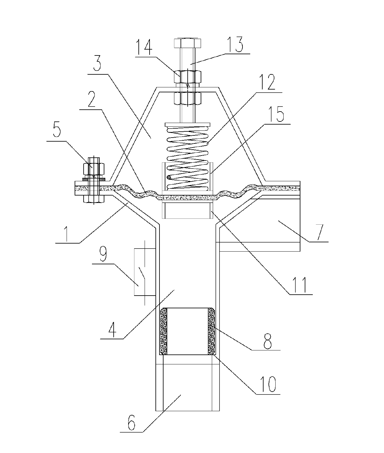
Figure 1 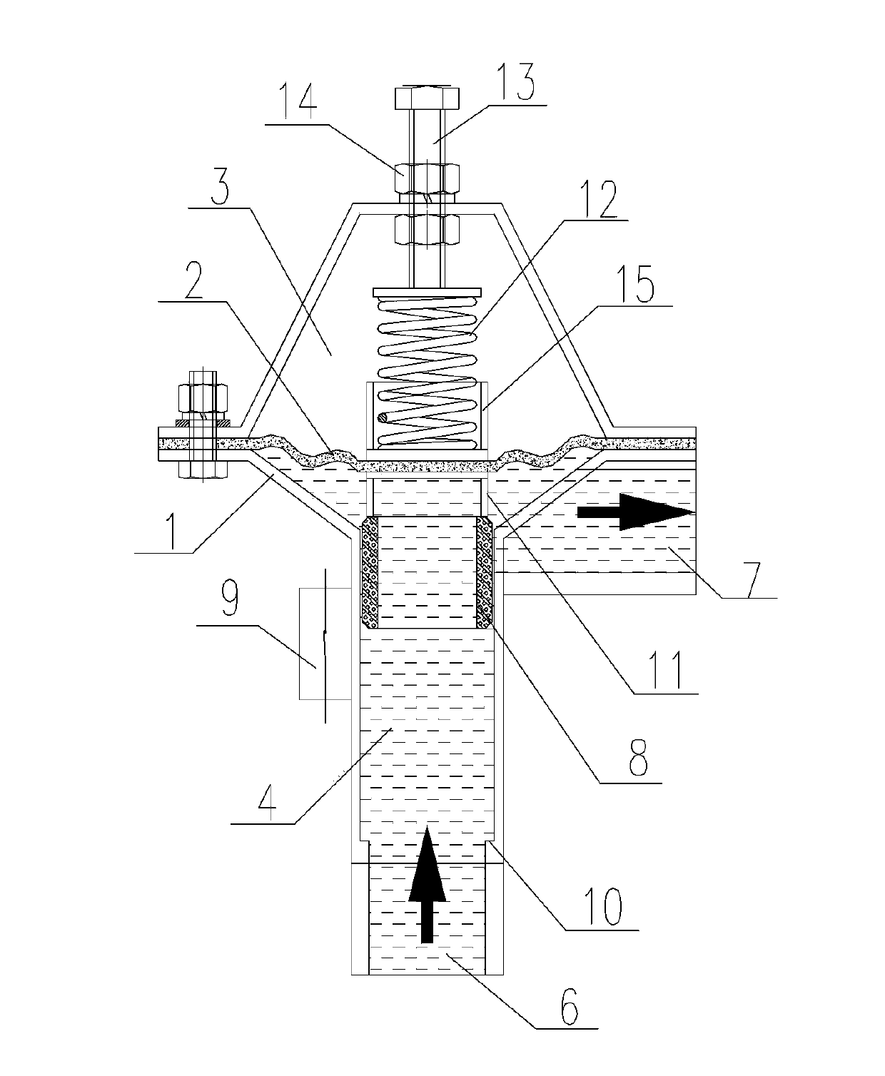
Figure 2 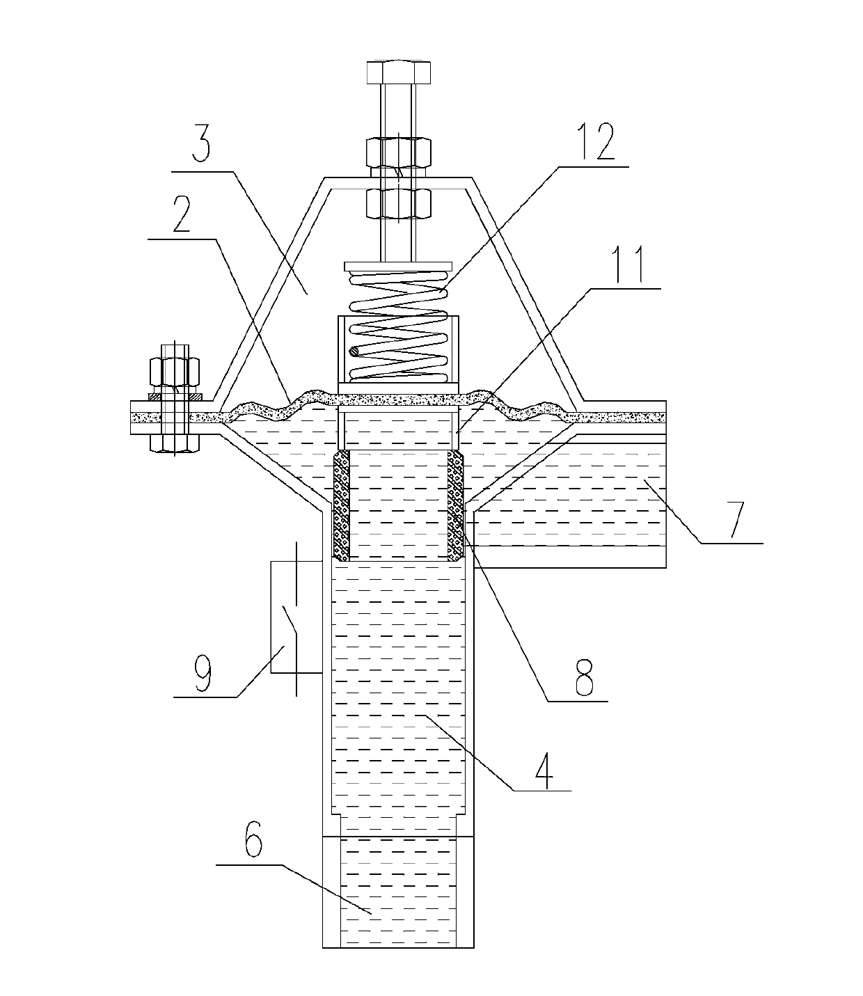
Figure 3
Abstract
Description
Technical field
[0001] The invention relates to a water pump control device, belonging to the technical field of water pump control. Background technique
[0002] At present, the automatic control of the water pump generally adopts the pressure switch, the flow switch, and the water level detection of the water source to control the start and stop of the water pump. The pressure switch is directly used to start and stop, because the pipeline can not maintain the pressure, frequent start and stop phenomena occur. In order to solve this problem, a method of adding a compressed air tank in the water outlet pipeline is adopted, but the system has a complicated structure and many parts and takes up a large space. Summary of the invention
[0003] The main purpose of the present invention is to solve the above-mentioned problems and shortcomings, and provide a water pump automatic control device with high integration, small space occupation and simple and convenient control.
[0004] In...
Examples
Embodiment Construction
[0020] The present invention will be further described in detail below in conjunction with the drawings and specific embodiments:
[0021] Such as Figure 1 to Figure 3 As shown, the automatic control device for a water pump of the present invention includes a casing 1, and the inside of the casing 1 is divided into two upper and lower chambers separated from each other by a diaphragm 2, which are an upper chamber 3 and a lower chamber 4, respectively. , The diaphragm 2 is located at the top of the lower cavity 4.
[0022] The housing 1 is provided with a water inlet 6 and a water outlet 7. The water inlet 6 is connected to the water outlet of a water pump (not shown in the figure) through a water pipe, and the water outlet 7 is connected to the water inlet of the water equipment through a water pipe. In this embodiment, the water inlet 6 and the water outlet 7 are in communication with the lower cavity 4, and the water from the water pump enters the lower cavity 4 through the wat...