Water hammer protection method and device for a centrifugal pump when the pump is stopped
A pump-stopping water hammer and protective device technology, which is applied to the components of the pumping device for elastic fluids, pump components, variable displacement pump components, etc. Increase the cost of the water transfer system and other issues to achieve the effect of increasing equipment investment, prolonging the time to start inversion, and reducing energy consumption for water delivery
- Summary
- Abstract
- Description
- Claims
- Application Information
AI Technical Summary
Problems solved by technology
Method used
Image
Examples
Embodiment 1
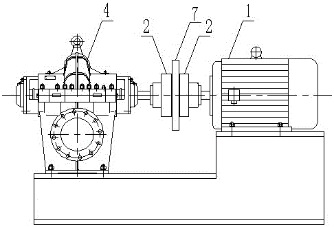
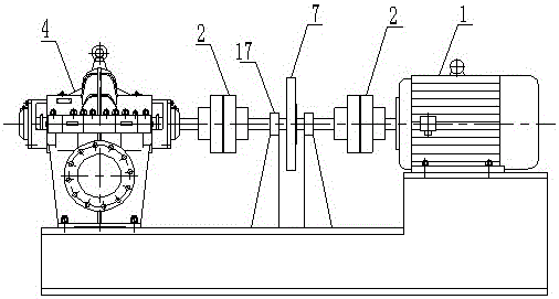
[0023] A water hammer protection method for a centrifugal pump when the pump is stopped, which is to set the water pump main shaft and / or the motor main shaft of the water pump unit in the form of shaft output at both ends, and connect an electromagnetic clutch to the outer shaft end of the water pump main shaft and / or the motor main shaft, And the inertial flywheel is connected to the rear end of the electromagnetic clutch. When the water pump unit is working, the electromagnetic clutch is separated. When the water pump unit is powered off and the pump is stopped, the electromagnetic clutch absorbs and applies an inertial moment to the water pump unit and / or the motor through the inertial flywheel. To increase the moment of inertia to achieve water hammer protection.
[0024] The electromagnetic clutch is a normally closed electromagnetic clutch.
Embodiment 2
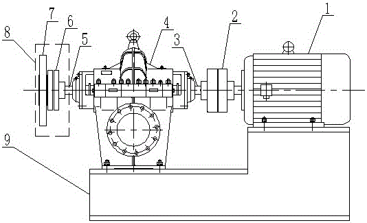
[0026] as attached image 3 As shown, a water hammer protection device for centrifugal pumps, including a water pump 4 and a motor 1 connected to the water pump 4, the water pump 4 is a horizontal centrifugal pump, which adopts a shaft structure at both ends, and the inner side of the water pump 3 The coupling 2 is connected with the motor 1, and the outer shaft 5 of the water pump is connected with an electromagnetic clutch 6, and the rear end of the electromagnetic clutch 6 is connected with an inertial flywheel 7. A protective cover 8 is provided outside the inertial flywheel 7 . Both the water pump 4 and the motor 1 are arranged on the frame 9 .
[0027] The electromagnetic clutch 6 is a normally-closed electromagnetic clutch, which pulls in when it is powered off, and separates when it is powered on. It can be controlled by the 24V or 90V DC power supply of the pumping station. The inertia flywheel 7 can adopt a spoke type or a disc type. In order to facilitate the con...
Embodiment 3
[0031] as attached Figure 4 As shown, a centrifugal pump water hammer protection device includes a water pump 4 and a motor 1 connected to the water pump 4 , and the water pump 4 and the motor 1 are both arranged on a frame 9 . The motor 1 adopts a shaft structure at both ends. The inner shaft 10 of the motor is connected to the water pump 4 through the coupling 2. The outer shaft 11 of the motor is connected to the electromagnetic clutch 6, and the rear end of the electromagnetic clutch 6 is connected to an inertial flywheel 7. A protective cover 8 is provided outside the inertial flywheel 7 .
[0032] Described electromagnetic clutch 6 is a normally closed type, flange type electromagnetic clutch, and the electromagnetic clutch pulls in when power off, and separates when power is turned on, and it can be controlled by the 24V or 90V DC power supply of the pumping station. The inertia flywheel 7 can adopt a spoke type or a disc type, which is connected with the electromagne...
PUM
 Abstract
Description
Claims
Application Information
 - R&D
- Intellectual Property
- Life Sciences
- Materials
- Tech Scout
- Unparalleled Data Quality
- Higher Quality Content
- 60% Fewer Hallucinations
Browse by: Latest US Patents, China's latest patents, Technical Efficacy Thesaurus, Application Domain, Technology Topic, Popular Technical Reports.
© 2025 PatSnap. All rights reserved.Legal|Privacy policy|Modern Slavery Act Transparency Statement|Sitemap|About US| Contact US: help@patsnap.com


