Transmission line single-phase grounding fault single-end ranging method

A single-phase ground fault, single-end ranging technology, applied in the direction of the fault location, can solve the problem of affecting the fault location accuracy, single-end impedance method ranging accuracy is not high, poor accuracy and other problems

Active Publication Date: 2014-03-12
TSINGHUA UNIV
View PDF8 Cites 29 Cited by
  • Summary
  • Abstract
  • Description
  • Claims
  • Application Information

AI Technical Summary

Problems solved by technology

However, the single-ended impedance method is affected by the fault resistance and the impedance of the opposite end system, and the accuracy is poor; the improved methods include: power frequency impedance method, differential equation solution method, zero-sequence current phase correction method, fault current phase correction method, and quadratic solution Equation methods, etc., all assume that the current at the fault point is in the same phase as the current at the measuring point, or that the line-to-end system impedance is known, but in the actual system, the above assumptions are difficult to hold, so the ranging accuracy of the single-ended impedance method is not high
[0004] The voltage and current information used by the single-ended impedance method described above is information on a time section, that is, the information on the time section after a fault until the circuit breaker trips. It is impossible to accurately calculate the impedance information of the opposite end system, which directly affects Accuracy of fault location

Method used


Image

  • Transmission line single-phase grounding fault single-end ranging method
  • Transmission line single-phase grounding fault single-end ranging method
  • Transmission line single-phase grounding fault single-end ranging method

Examples


Embodiment Construction

[0034] The embodiment of the method for single-end distance measurement of single-phase ground fault of transmission line based on fault isolation multi-time section information proposed by the present invention is described in detail as follows:

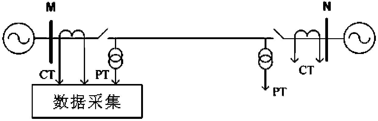
[0035] A 1000kV UHV transmission system model applying the present invention is shown in the accompanying drawings, the line length is 400km, and the line parameter values ​​are shown in Table 1; the system impedance parameters of the M and N sides are as follows, and the power supply phase corner of the N side is M The side is 20 degrees, and the M side and N side potentials are 1.1062 and 1.1069 times the rated voltage respectively. The device for collecting data applying the method of the present invention is installed on the M side, and the voltage and current come from the voltage transformer and the current transformer on the line side respectively. The simulated fault type is A-phase ground fault, the fault distance is 150km ...


PUM


Abstract

A transmission line single-phase grounding fault single-end ranging method belongs to the field of power system protection and control. According to the method of the invention, positive, negative and zero sequence voltage and current phasors of a line during the time section between the occurrence of a single phase grounding fault and single phase tripping and the time section between single phase tripping and reclosing are measured at a substation protection installation site and are used as input. The initial value of fault distance is set from 0 to the overall length of the line with delta1 as the step length, and the initial value of transition resistance starts from 1 ohm and increases to 1000 ohms with 1 ohm as the step length. For each combination of the values of fault distance and transition resistance, the equivalent electromotive force values of a system at the opposite end of the line during the time section between the occurrence of the single phase grounding fault and single phase tripping and the time section after single phase tripping are respectively calculated, the sum of absolute errors of the equivalent electromotive force values is calculated, and the fault distance value corresponding to the minimum value of the sum of absolute errors is selected as the fault ranging distance. The method is high in precision, is not affected by distributed capacitive current, transition resistance, load and system impedance and has very high practical values.

Description

technical field [0001] The invention belongs to the technical field of power system protection and control, in particular to a method for single-end single-end distance measurement of single-phase grounding faults of transmission lines based on fault isolation multi-time section information. technical background [0002] Accurate distance measurement of transmission line faults can help shorten the line inspection time after a fault, speed up the troubleshooting of line faults and restore power supply, and is of great significance for improving the stability of the power system and ensuring the safe operation of the system. [0003] Fault location methods can be divided into single-ended and double-ended methods from the perspective of using electrical quantities. The double-ended method uses the electrical information at both ends of the line. In principle, it can achieve accurate fault location. However, in practical applications, it is affected by the reliability of doubl...

Claims


Application Information

Patent Timeline
Patent Type & Authority Applications(China)
IPC IPC(8): G01R31/08
Inventor 王宾耿建昭董新洲
Owner TSINGHUA UNIV
Why Eureka
Try Eureka