Automatic-mobile robot walking scope restriction system and restriction method thereof

A robot, self-moving technology, applied in control/regulation systems, non-electric variable control, radio wave measurement systems, etc., can solve problems such as cost increase, regression reflective marking failure, etc., and achieve long working hours, energy saving, and high sensitivity. Effect

Active Publication Date: 2014-03-12
ECOVACS ROBOTICS (SUZHOU ) CO LTD
View PDF7 Cites 36 Cited by
  • Summary
  • Abstract
  • Description
  • Claims
  • Application Information

AI Technical Summary

Problems solved by technology

In the third scheme, since the retroreflective markers are laid on the ground, the retroreflective markers are also prone to failure due to pollution. When the interval between the limited areas is large, it is nece

Method used


Image

  • Automatic-mobile robot walking scope restriction system and restriction method thereof
  • Automatic-mobile robot walking scope restriction system and restriction method thereof
  • Automatic-mobile robot walking scope restriction system and restriction method thereof

Examples


Embodiment 1

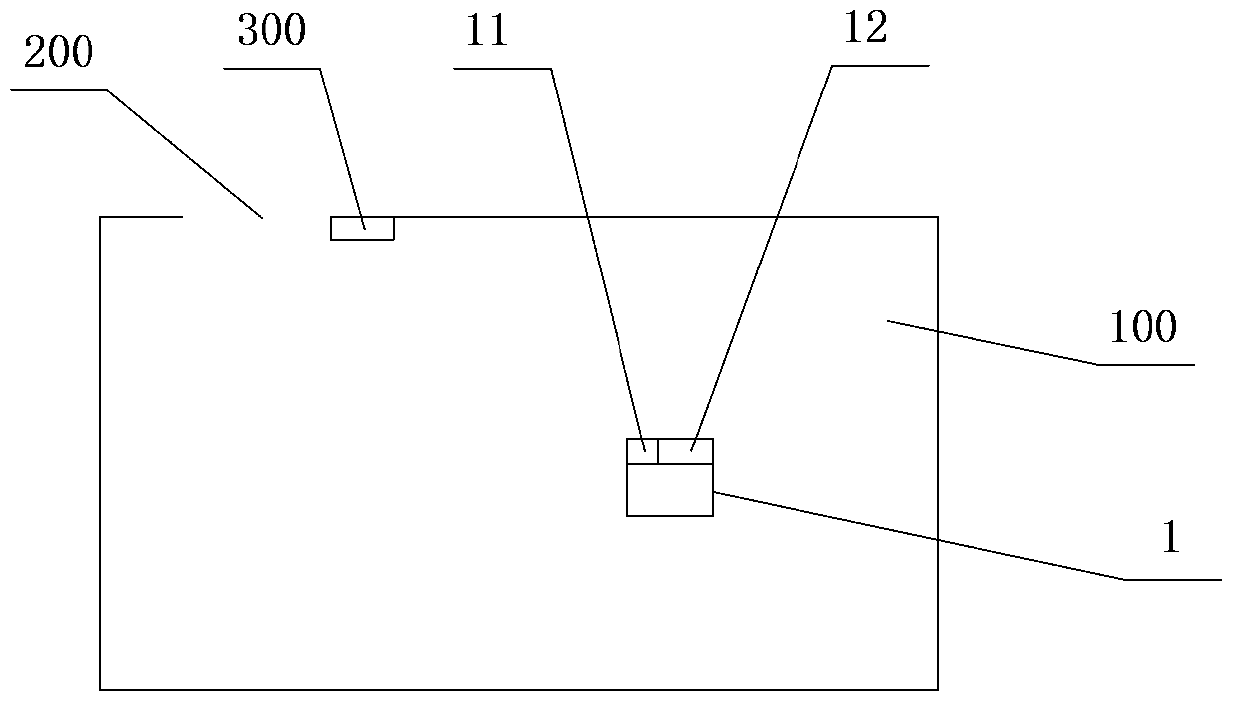
[0033] figure 1 It is a schematic diagram of setting position of boundary markers according to Embodiment 1 of the present invention. Such as figure 1 As shown, the present invention provides a system for limiting the walking range of an autonomous mobile robot, including: a limit marker 300 and an autonomous mobile robot 1 . The limit mark 300 is used to determine the limited boundary position of the working space 100, including retroreflective material, such as: retroreflective film. The self-mobile robot 1 walks and works in the working space 100 , including: a scanning range finder 12 and a control device 11 . The scanning range finder 12 forms a scanning plane by transmitting and receiving optical signals, and scans and measures the working space 100 . The control device 11 receives the scanning ranging signal from the scanning ranging instrument 12 and establishes a coordinate map of the working space 100 . The control device 11 determines the position of the limit m...

Embodiment 2

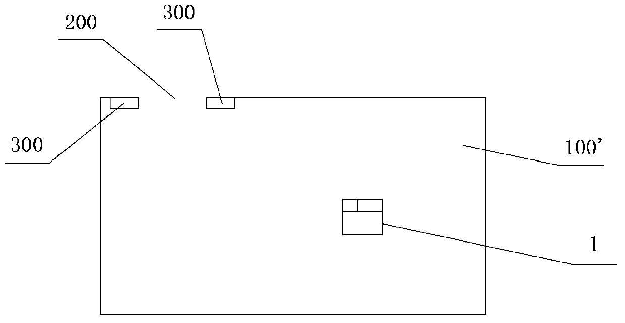
[0042] figure 2 It is a schematic diagram of setting the position of the limit mark in the second embodiment of the present invention. Such as figure 2 As shown, in this embodiment, the setting position of the limit mark 300 is also at the non-closed opening 200, but the difference from Embodiment 1 is that the limit mark 300 in this embodiment is set in pairs respectively at the non-closed opening 200 on both sides of the wall. During the rotation process of the self-mobile robot 1, the laser range finder performs map modeling on the room 100'. After modeling, the self-mobile robot 1 knows its own coordinate position no matter where it goes. At the same time, the self-mobile robot 1 The position of the boundary marker 300 is identified by the strength of the reflected signal. Line segments on the two boundary markers 300 respectively falling between any two points on the scanning plane at least partially form the boundary. That is to say, the straight line on the limit ...

Embodiment 3

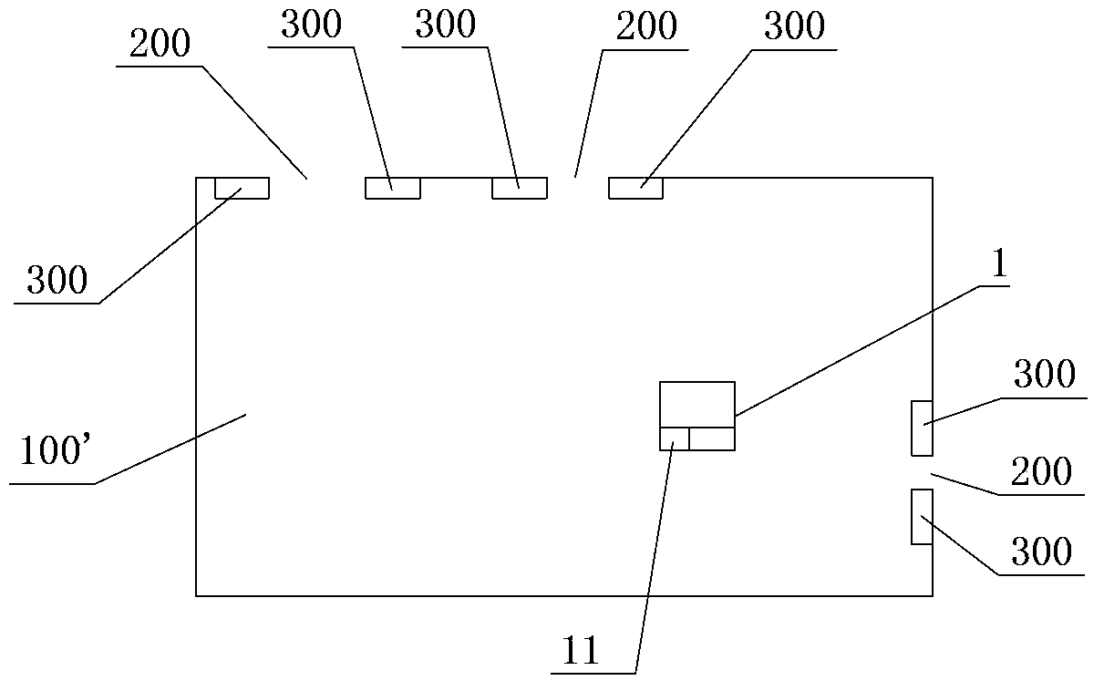
[0044] image 3 It is a schematic diagram of setting the position of the boundary mark 300 according to the third embodiment of the present invention. Such as image 3 As shown, in this embodiment, there are multiple non-closed openings 200, and at this time, there are correspondingly multiple limit marks 300, and each limit mark 300 is respectively set on the corresponding non-closed opening 200. one or both sides. The self-mobile robot 1 recognizes the position of the limit mark 300 through the reflected signal strength, and a virtual line segment is formed between any two points on any two limit marks 300 respectively falling on the scanning plane. In the control device 11, the threshold value of the width of the non-closed opening 200 is pre-stored, and the control device 11 compares the distance between the virtual line segment formed by any two adjacent limit marks 300 with the threshold value, and the two limit marks 300 whose distance is smaller than the threshold va...


PUM


Abstract

An automatic-mobile robot walking scope restriction system and a restriction method thereof are provided; the restriction system comprises the following structures: a boundary mark (300) used for determining restriction boundary positions of a work space (100), and the boundary mark comprises regression reflection material; an automatic-mobile robot (1) walking and working in the work space, and the robot comprises a scan range finder (12) sending and receiving light signals so as to form a scanning plane, thereby carrying out range finding and scanning process to the work space; the robot also comprises a control device (11) used for receiving scan and range finding signals of the scan range finder and setting up a coordinate chart of the work space. The control device receives the scan and range finding signals reflected from the boundary mark by the scan range finder, so the positions of the boundary mark are determined; the coordinates of the restricted boundary are determined according to the positions of the boundary mark, so the automatic-mobile robot can be controlled to work in an area in the restricted boundary. The automatic-mobile robot walking scope restriction system and the restriction method thereof can save energy, are long in effective work time, high in sensitivity and low in cost.

Description

technical field [0001] The invention relates to a system for limiting the walking range of a self-moving robot and a limiting method thereof, belonging to the technical field of small household electrical appliances. Background technique [0002] Self-cleaning mobile robots are widely used for their small size and flexible movement. When the existing cleaning self-mobile robot cleans the room 100', it is usually necessary to limit the working area of ​​the self-mobile robot, such as limiting cleaning only to the hall or bedroom. At present, there are mainly three schemes for limiting the working area: Scheme 1: the virtual wall generating device limits the working area. For example: U.S. public document US6690134 reveals that the virtual wall generating device emits a beam of light as a virtual wall, and after the detector of the self-mobile robot detects the beam, it retreats away from the beam, so that the self-mobile robot works within the limit of the virtual wall gener...

Claims


Application Information

Patent Timeline
IPC IPC(8): G05D1/02G01S17/08
CPCG01S17/42G05D1/02G01S17/08G05D1/0238G05D1/0244G05D1/0274G05D2201/0203
Inventor 汤进举
Owner ECOVACS ROBOTICS (SUZHOU ) CO LTD
Why Eureka
Try Eureka