Three-wheel planar position finder

A locator, three-wheeled technology, applied in the direction of control using feedback, can solve problems such as no communication function

Inactive Publication Date: 2014-03-12
BEIHANG UNIV
View PDF3 Cites 14 Cited by
  • Summary
  • Abstract
  • Description
  • Claims
  • Application Information

AI Technical Summary

Problems solved by technology

The disadvantage they have in common is that they are highly specific. As far as the communicatio...

Method used


Image

  • Three-wheel planar position finder
  • Three-wheel planar position finder
  • Three-wheel planar position finder

Examples


Embodiment Construction

[0034] The present invention will be further described below in conjunction with the drawings.

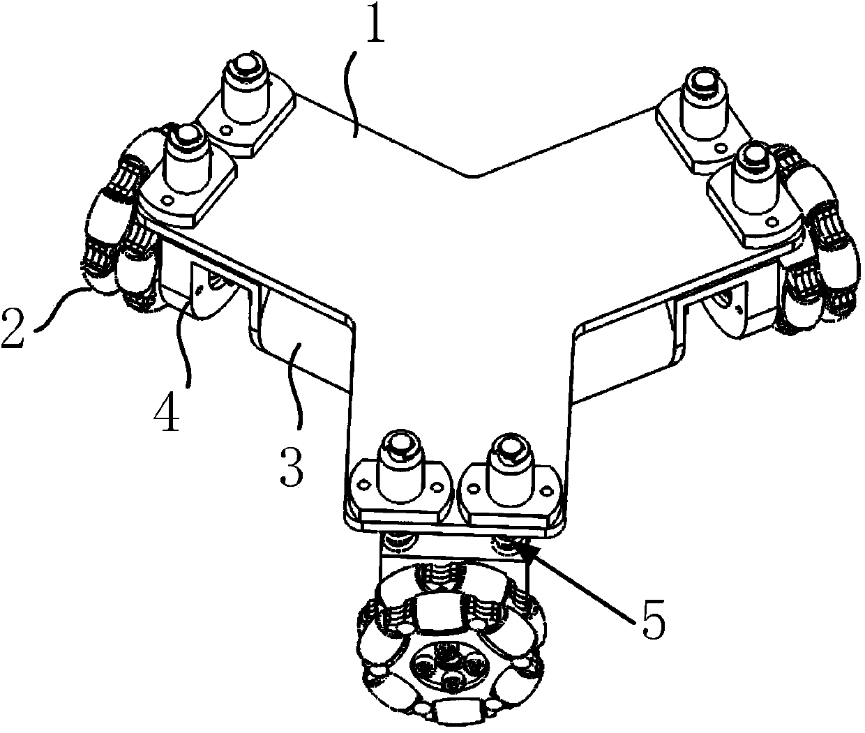
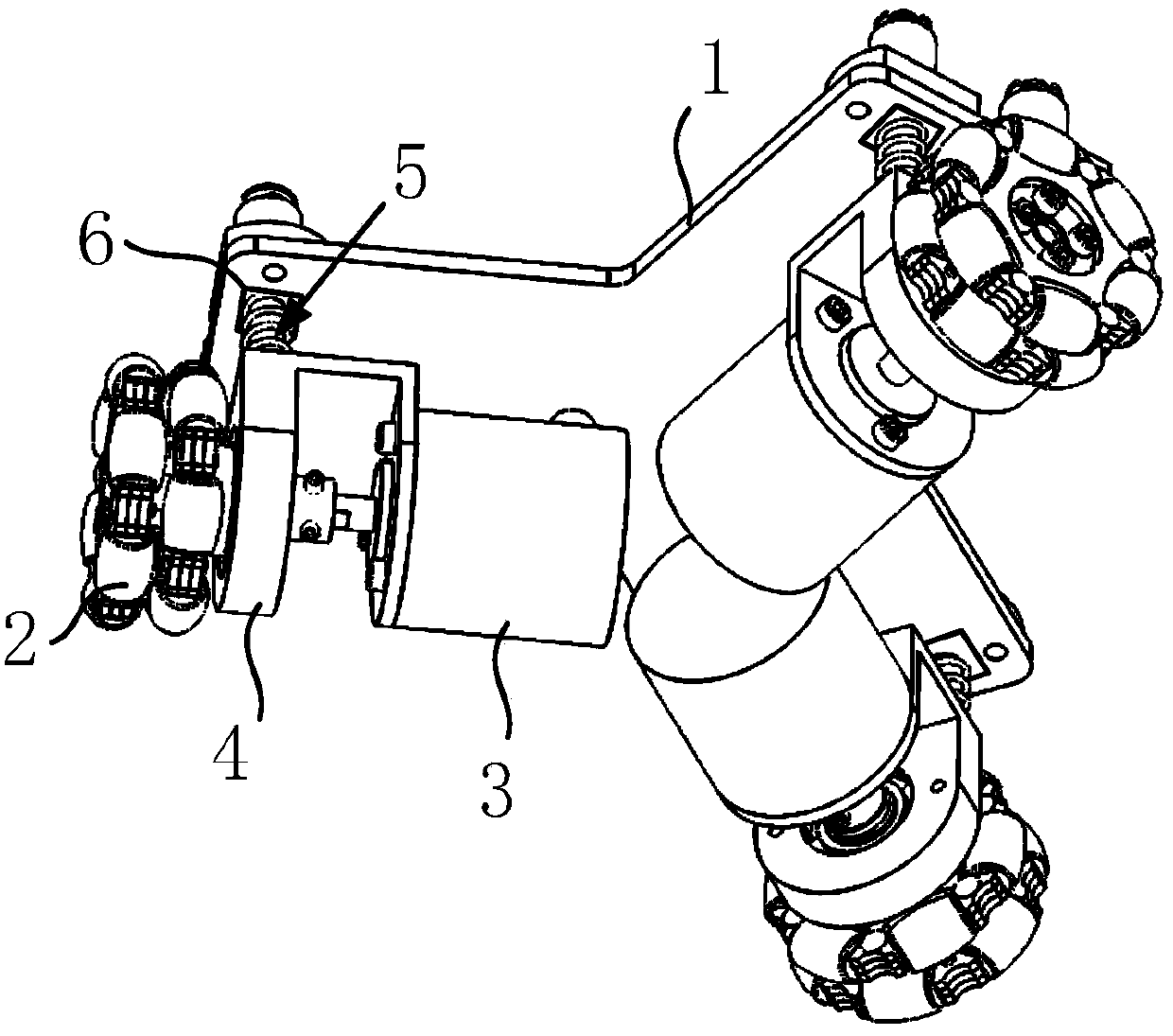
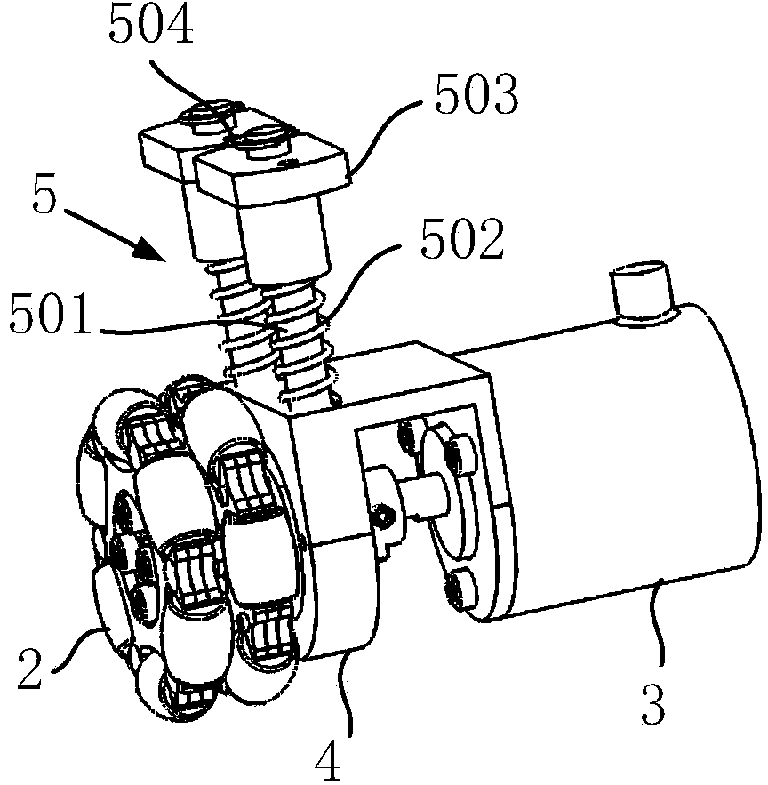
[0035] The three-wheeled plane positioning instrument of the present invention includes a mechanical transmission part and an electronic control part, such as figure 1 , figure 2 , image 3 As shown, the mechanical transmission part is a three-wheel passive planar omnidirectional mobile chassis designed with universal wheels, which specifically includes the installation plane 1, the universal wheel 2, the incremental photoelectric encoder 3, the encoder bracket 4, and the reducer. Vibration structure 5 and piezoresistor 6. The electronic control part includes a data acquisition module 7, a data processing module 8 and a working mode setting module 9, such as Figure 4 Shown.

[0036] In the mechanical transmission part, the upper surface of the installation plane 1 is used to fix the main power equipment, and there are three encoder brackets 4 uniformly installed in the circumferential...


PUM


Abstract

The invention discloses a three-wheel planar position finder. Three universal wheels are axially uniformly designed at the lower surface of a mounting plane, and angular displacement signals of the three universal wheels are respectively measured by three photoelectric coders and are converted into pulse signals for outputting; damping structures are designed between the mounting plane and the three universal wheels. A variable resistor is arranged between a damping spring in each damping structure and the mounting plane; the variable resistors are used for measuring the pressure signals applied by the damping springs, and then the rotary states of the universal wheels are represented; when two or all of the pressure signals corresponding to the three universal wheels are larger than a threshold value, digit data are obtained by adopting a two-wheel or three-wheel algorithm. The three-wheel planar position finder has the advantages that the vibration degree of main power equipment can be output by the data of a pressure sensor, the rotary states of the universal wheels can be judged, the operation can be switched to the two-wheel algorithm when one universal wheel leaves the ground, and the error possibly caused in the time period can be compensated.

Description

Technical field [0001] The invention belongs to the technical field of electronic information and automatic control, and specifically, is a three-wheel type plane positioning instrument. Background technique [0002] With the development of science and technology, the appearance of photoelectric encoder has accelerated the process of industrial automation to a certain extent. For the incremental photoelectric encoder, the mechanical rotation of the connecting device can be converted and the pulse signal can be output, and the upper computer can process it (usually integrating) to obtain the position information. But for this type of photoelectric encoder, the output pulse is expressed by two A-phase and B-phase signals with a phase difference of π / 2 to indicate the number of forward and reverse pulses. During forward rotation, the A-phase output pulse leads B Phase output pulse π / 2; when reverse, the A phase output pulse lags behind the B phase pulse π / 2. [0003] For users or de...

Claims


Application Information

Patent Timeline
IPC IPC(8): G05D3/12
Inventor 鄢立夏马保离谢文静雷晨
Owner BEIHANG UNIV
Why Eureka
Try Eureka