[0055] All the features disclosed in this specification, or all disclosed methods or steps in the process, except for mutually exclusive features and/or steps, can be combined in any manner.
[0056] Any feature disclosed in this specification, unless specifically stated, can be replaced by other equivalent or equivalent alternative features. That is, unless otherwise stated, each feature is just one example of a series of equivalent or similar features.
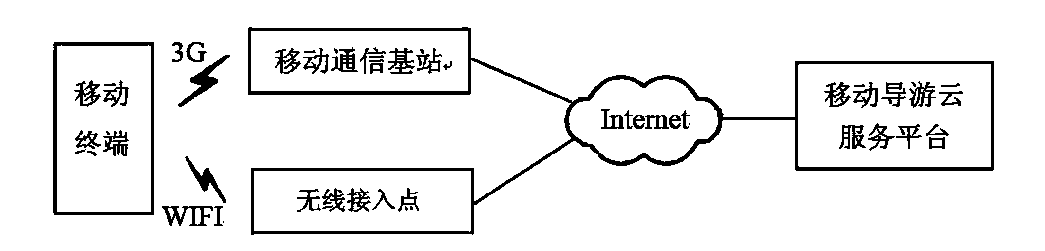
[0057] Such as figure 1 , The smart guide device based on the mobile Internet in the present invention includes a mobile client module and a guide service module;
[0058] The mobile client module is installed on a mobile terminal, such as a smart phone, a notebook computer, and a tablet computer, and is used to control the mobile terminal to collect location information of a scenic spot, and then connect the scenic spot through a mobile network, such as a 3G wireless network or a wifi wireless network. The positioning information is transmitted to the tour guide server; and the mobile terminal is controlled to present the tourist information resources of the scenic spots pushed by the travel service module to the user;
[0059] The travel service module is installed on the tour guide server, which can also be called a mobile tour guide cloud service platform, and is used to store the tourist information resources corresponding to each scenic spot ID in the storage area of the tour guide server; extract the scenic spot ID in the scenic spot location information , Search the scenic spot tourist information resource corresponding to the scenic spot ID in the storage area; and push the scenic spot tourist information resource corresponding to the scenic spot ID to the mobile terminal through the mobile network.
[0060] The method for implementing the smart guide by the above device includes:
[0061] Step 1: Store the tourist information resources corresponding to each scenic spot ID in the storage area of the tour guide server;
[0062] Step 2: The mobile terminal collects scenic spot location information, and then transmits the scenic spot location information to the tour guide server via the mobile network;
[0063] Step 3: The tour guide server extracts the scenic spot ID in the scenic spot location information, and searches the storage area for the scenic spot tourism information resource corresponding to the scenic spot ID;
[0064] Step 4: The tour guide server pushes the tourist information resource of the scenic spot corresponding to the scenic spot ID to the mobile terminal via the mobile network;
[0065] Step 5: The mobile terminal presents the tourist information resources of the scenic spots to the user.
[0066] In one embodiment, the tourist information resource of the scenic spot includes text introduction of the scenic spot, pictures of the scenic spot, commentary and animation of the scenic spot. Such as figure 2 , Convert the text introduction of the scenic spots into PDF format documents, the scenic spots pictures into JPEG format files, and the scenic spots commentary into MP4 format files. If the scenic spot has animation, you need to prepare an animation file in swf format in advance. Upload the pre-prepared tourist information resources (PDF documents, JPEG pictures, MP4 videos, swf animations) to the mobile guide server and store them in its storage area. The above-mentioned tourist information resources of each scenic spot correspond to the scenic spot ID.
[0067] In another embodiment, the scenic spot location information may be scenic spot voice signals, scenic spot QR codes, scenic spot photos, or scenic spot GPS information. The mobile terminal collects the scene information of tourists in the scenic spot through multiple dimensions through voice input, QR code scanning, photographing and GPS positioning, and sends it to the remote tour guide server in real time via 3G and WIFI.
[0068] Such as image 3 A specific way for the tour guide server to extract the scenic spot ID is as follows:
[0069] First determine whether the received scenic spot location information is a scenic spot voice signal? If so, call the voice recognition service, extract the name of the scenic spot, and query the database to obtain the scenic spot ID, such as Figure 4.
[0070] If it is not a scenic spot voice signal, is it judged whether the received scenic spot location information is a scenic spot QR code? If yes, start the QR code query service to query the tourist attraction ID, such as Figure 5.
[0071] If it is not the QR code of the scenic spot, is it judged that the received scenic spot location information is a scenic spot photo? If yes, use the image positioning algorithm to extract the ID of the tourist attraction, such as Image 6.
[0072] If it is not a scenic spot photo, is it judged whether the received scenic spot location information is scenic spot GPS information? If so, call the location query service to extract the tourist spot ID.
[0073] Such as Image 6 , A specific implementation of scenic spot image positioning is as follows: first preprocess the scenic spot photos, the image preprocessing method can be normalization processing, smoothing denoising, image segmentation based on edge detection, that is, the scene is removed from the image by edge detection. Separated from the background, etc.; then extract features, image features can be gray histogram, shape factor and moment invariant, etc.; finally match the image features with the pre-stored scenic spot reference image in the database, and finally output the scenic spot ID.
[0074] If the tourist's scenic spot can receive network and GPS signals, the mobile terminal can obtain the tourist's latitude and longitude information in real time, or called scenic spot GPS information. The method to extract the scenic spot ID from the GPS information of the scenic spot is as follows:
[0075] Suppose, the longitude and latitude of a certain scenic spot ID is (LonA, LatA), the longitude and latitude of the current location of tourist B (LonB, LatB), according to the reference of 0 degree longitude, the east longitude takes the positive value of longitude (Longitude), the west longitude takes the negative longitude Value (-Longitude), 90-Latitude for north latitude (90-Latitude), and 90+latitude for south latitude (90+Latitude), then the two points after the above processing are counted as (MLonA, MlatA) and (MLonB) ,MLatB). According to the triangle derivation, the formula for calculating the distance between two points can be obtained as follows:
[0076] C=sin(MLatA)*sin(MLatB)*cos(MLonA-MLonB)+cos(MLatA)*cos(MLatB)
[0077] Distance=R*Arccos(C)*Pi/180, where R is the average radius of the earth (R=6371.004 kilometers).
[0078] If the distance between the tourist and the scenic spot is within the calculation error (for example, 5 meters or 10 meters), the scenic spot positioning success message will be returned. Otherwise, the scenic spot location fails.
[0079] The present invention also provides a method for realizing an intelligent tour guide capable of augmented reality. Augmented Reality (AR) technology embeds virtual scenes into real scenes through computer technology, and superimposes real scenes and virtual scenes in real time. In the same picture or space, the virtual world and the real world can coexist harmoniously. Augmented reality is an important branch of virtual reality technology, which is characterized by the consistent combination of virtual and real spaces and real-time interaction.
[0080] Such as Figure 7 , Based on the mobile terminal augmented reality virtual tour guide method on the basis of the foregoing embodiment, the step 2 also includes: the mobile terminal takes a picture or video of the tourist attraction where the user is located to obtain the real scene, and then transmits it to the tour guide server through the mobile network ;
[0081] The step 3 also includes: registering and positioning the real scene; the augmented reality system must be able to detect the position and direction angle of the observer (or mobile terminal camera) relative to the real scene in real time, and the imaging system (camera) Internal parameters (focal length and pixel aspect ratio, etc.), so as to be able to determine the real-time mapping position of the virtual scene to be added based on this information, and display this information in the correct position in the image in real time. That is to say, from the user's point of view, the virtual object and the real scene should maintain the geometric consistency of the three-dimensional Euclidean space, no matter from any angle.
[0082] Step 3 also includes extracting virtual scene graphics from the virtual scene library on the tour guide server, which is also called scene generation. Scene generation is responsible for providing virtual scene graphics of tourist attractions for the augmented reality system. Here, we first use 3DS (3DS is a 3D modeling software tool) to build its 3D virtual scene library for specific tourist attractions. Subsequently, according to the location and state of the tourist, the virtual scene is loaded from the virtual scene library in real time.
[0083] Step 3 also includes virtual and real scene synthesis, that is, the virtual scene and the real scene are merged on the OSG virtual display platform according to the result of registration and positioning, to obtain a merged image;
[0084] The step 4 also includes: the tour guide server pushes the fused image to the mobile terminal through the mobile network;
[0085] The step 5 also includes: the mobile terminal presents the merged image to the user.
[0086] The aforementioned registration positioning, scene generation, and virtual and real scene synthesis are all existing technologies.
[0087] At present, registration positioning mainly includes two methods of tracking and registration with and without marking points. Although the manual registration and positioning algorithm for landmarks is relatively mature and perfect, it is necessary to add landmarks of various shapes and colors in tourist places, which is not allowed in many national-level protected scenic spots. Therefore, the present invention adopts natural landmarks. Object registration and positioning algorithm.
[0088] The basic steps of the algorithm are as follows:
[0089] 1) Obtain a real scene picture taken by the mobile terminal, or intercept a real scene image from the video stream taken by the mobile terminal, and use it as a marker;
[0090] 2) Use image recognition algorithms to extract feature points from marker images:
[0091] At present, there are many image recognition algorithms used to extract feature points, and the present invention uses the SURF algorithm to extract feature points of the scene. At present, among the image feature point extraction algorithms, the SIFT algorithm is considered the most effective and commonly used algorithm. However, without the help of hardware acceleration and dedicated graphics processors, it is difficult for the SIFT algorithm to meet the requirements of real-time processing. As a simplified implementation of the SIFT algorithm, the SURF algorithm increases the calculation speed by 3 times, while meeting the feature point detection of scale and rotation invariance.
[0092] 3) Complete the transformation from the marker coordinate system to the camera coordinate system:
[0093] Such as Figure 8 , Suppose, R is the rotation matrix, T is the translation vector, O is the vector whose values are all zero, then the marker coordinate system (x m ,y m ,z m ) T To the camera coordinate system (x c ,y c ,z c ) T The matrix transformation can be expressed as:
[0094] x c y c z c 1 = R T O 1 x m y m z m 1 = r 1 r 2 r 3 t 1 r 4 r 5 r 6 t 2 r 7 r 8 r 9 t 3 0 0 0 1 x m y m z m 1
[0095] 4) Complete the transformation from the camera coordinate system to the actual scenic spot image coordinate system:
[0096] Assuming that there is no distortion inside the camera of the mobile terminal, and the optical axis is perpendicular to the imaging plane and passing through the center of the plane, the imaging model of the camera can be described as
[0097]
[0098] Where (x d , Y d ) Is the coordinate of an object point P in the camera coordinate system in the imaging plane coordinate system, and f is the focal length of the camera.
[0099] In fact, the lens of the mobile terminal camera will inevitably cause image distortion. First consider the linear distortion model inside the camera: the center origin of the imaging plane-the projection center (that is, the principal point of the image) has shifted on the image plane, such as Picture 9 , That is, the x-axis and y-axis corresponding to the image plane also have corresponding scale scaling, and the scaling factor k is introduced x And k y.
[0100] This distortion process can be described as
[0101] u = k x x + u o v = k y y + v 0
[0102] among them,
[0103] x = X c f z c y = Y c f z c
[0104] (X, y) is the coordinate of the object point P in the camera coordinate system in the imaging plane coordinate system, (u, v) is the position of a certain point in space in the image plane coordinate system, (u 0 , V 0 ) Is the principal point coordinates of the image (that is, the focal point between the optical axis of the camera and the image plane), (x c ,y c ,z c ) Is the coordinate of the object point P in the camera coordinate system.
[0105] If the image plane is not only distorted, but also distorted, the coordinate axis is not orthogonal, such as Picture 10 , On the basis of distortion 1, the distortion process can be described as
[0106] u = k x - k x y cot θ + u 0 v = y k y sin θ + v 0
[0107] make,
[0108] f x = f k x f y = k y sin θ s = f y f x
[0109] Then, the distortion process inside the camera of the mobile terminal can be expressed as
[0110] z c u v 1 = f x s u 0 0 f y v o 0 0 1 x c y c z c = k x c y c z c
[0111] Here,
[0112] k = f x s u 0 0 f y v o 0 0 1
[0113] k is related to the internal structure of the camera and is called the internal parameter matrix of the camera. f x , F y Are the scale factors of the camera in the u and v axis directions, s is the distortion factor of the camera, and θ is the torsion angle of the image plane.
[0114] Using the above registration and positioning algorithm, the virtual scene of the scenic spot can be firmly fixed to the real scene, and the integration of the virtual scene and the real scene can be realized.
[0115] The present invention is not limited to the foregoing specific embodiments. The present invention extends to any new feature or any new combination disclosed in this specification, and any new method or process step or any new combination disclosed.