Two-module redundancy configuration memory unit circuit used in programmable logic device

A technology of configuration storage and programming logic, applied in information storage, static memory, digital memory information, etc., to achieve the effect of improving the anti-single event flip threshold

Active Publication Date: 2014-03-12
INST OF ELECTRONICS CHINESE ACAD OF SCI
View PDF7 Cites 9 Cited by
  • Summary
  • Abstract
  • Description
  • Claims
  • Application Information

AI Technical Summary

Problems solved by technology

However, in some applications, the configuration memory unit SRAM bit state in the FPGA is prone to be flipped by single event radiation

Method used


Image

  • Two-module redundancy configuration memory unit circuit used in programmable logic device

Examples


Embodiment Construction

[0017] In order to make the object, technical solution and advantages of the present invention clearer, the present invention will be described in further detail below in conjunction with specific embodiments and with reference to the accompanying drawings.

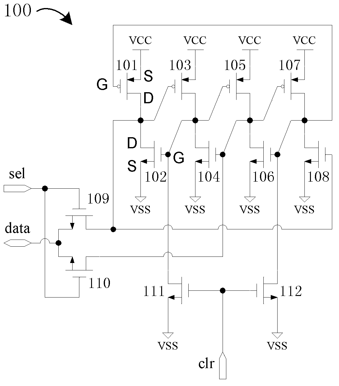
[0018] figure 1 It is a schematic diagram of a dual-mode redundant configuration storage unit circuit according to an embodiment of the present invention, such as figure 1 As shown, the dual-mode redundant configuration storage unit circuit 100 for programmable logic devices includes: 4 levels of 4 PMOS transistors 101, 103, 105, 107 and 4 NMOS transistors 102, 104, 106, 108 Interlocking storage unit, 2 transmission tubes 109 and 110, and 2 zeroing tubes 111 and 112, wherein:

[0019] The first PMOS transistor 101 and the first NMOS transistor 102 form a first-level interlock storage unit, the second PMOS transistor 103 and the second NMOS transistor 104 form a second-level interlock storage unit, and the third PMOS tran...


PUM


Abstract

A disclosed two-module redundancy configuration memory unit circuit used in a programmable logic device comprises a four-level interlocking memory unit consisting of four PMOS tubes and four NMOS tube, tow transmission tubes and two reset tubes. The two-module redundancy configuration memory unit circuit is capable of satisfying the configuration requirements of the programmable logic device by employing MOS tubes as less as possible, and improving the single event upset resistant threshold value of the programmable logic device.

Description

technical field [0001] The invention belongs to the technical field of integrated circuits, in particular to a dual-mode redundant configuration storage unit circuit for programmable logic devices. Background technique [0002] Since the 1970s, with the development of microelectronics technology, various types of general-purpose programmable logic devices (PLDs) have emerged. Among them, an FPGA configured with a storage unit SRAM based on device programming is widely used. Users can implement the required logic functions on SRAM through software, instead of having to design and manufacture ASIC chips by themselves. FPGA is a kind of high-density complex PLD. It consists of many independent programmable logic blocks, programmable interconnects, and programmable input / output blocks. Connections between logic blocks and with I / O blocks are made through programmable interconnect switches. Programmable resources can be controlled by downloading the configuration code stream ...

Claims


Application Information

Patent Timeline
Patent Type & Authority Applications(China)
IPC IPC(8): G11C11/413
Inventor 屈小钢杨海钢
Owner INST OF ELECTRONICS CHINESE ACAD OF SCI
Why Eureka
Try Eureka