
Double-sided flux switching permanent magnet linear motor

A permanent magnet linear motor, magnetic flux switching technology, applied in the direction of electrical components, electromechanical devices, electric components, etc., can solve the problems of increasing the weight of moving parts, increasing the cost of system engineering, increasing the weight of the primary iron core of the motor, and reducing the thrust Ripple, primary weight reduction, lower manufacturing cost effects

Active Publication Date: 2014-03-12
JIANGSU UNIV
View PDF3 Cites 8 Cited by
  • Summary
  • Abstract
  • Description
  • Claims
  • Application Information

AI Technical Summary

Problems solved by technology

Traditional flux switching permanent magnet motors usually use a "C" or "E" structure primary core unit, and the permanent magnet is installed between the two primary cores, while the armature winding is installed in a "C" or "E" In the E” type primary core unit, the weight of the primary core of the motor is virtually increased, especially for long secondary and short primary applications such as rail transit, which will greatly increase the weight of the entire moving part, which not only increases the engineering cost of the system, and will affect the dynamic performance of the system
[0003] The thrust of the motor is often directly related to the size of the air gap area. The traditional bilateral linear motor is basically a simple superposition of two unilateral linear motors, and the effect of improving parameters such as thrust density is not obvious.

Method used


Image

  • Double-sided flux switching permanent magnet linear motor

Examples


Embodiment Construction

[0021] The present invention will be further described below in conjunction with the accompanying drawings.

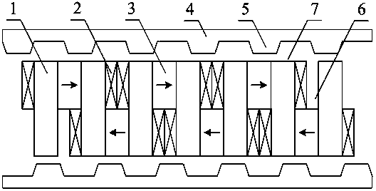
[0022] see figure 1 , The double-sided flux switching permanent magnet linear motor provided by the present invention is suitable for low-speed and high-thrust working conditions, and can be used as a direct-drive motor to run in an electric or power generation state, and its structure includes a motor primary and a motor secondary.

[0023] The motor primary includes a primary iron core 1, an armature winding 2 and a permanent magnet 3; the primary iron cores 1 are uniformly and dispersedly arranged to form a cogged structure of the primary part.

[0024] The primary iron core 1 is a "1"-shaped iron core. By changing the shape of the pole shoes of the primary iron core, the waveform of the induced potential of the motor can be optimized to reduce the thrust ripple of the motor.

[0025] The permanent magnets 3 are placed in the primary slots, and the adjacent permane...


PUM


Abstract

The invention discloses a double-sided flux switching permanent magnet linear motor. The double-sided flux switching permanent magnet linear motor comprises a motor primary side and a motor secondary side, wherein the motor primary side comprises primary cores, armature windings and permanent magnets, a serrated groove structure is formed by the scattered arrangement of the primary cores, the adjacent permanent magnets are respectively arranged next to the two sides of the primary cores alternately, trunkings are formed in an upper-lower alternating way, the magnetizing directions of the adjacent permanent magnets are opposite, the armature windings are arranged in the trunkings, and a concentrated winding structure is formed through the spanning arrangement of a coil of one armature winding over one permanent magnet and two primary cores; the motor secondary side comprises secondary cores and secondary salient poles, the positions of the secondary salient poles are staggered, and a clearance is arranged between the motor primary side and the motor secondary side. A yoke core is not required by the motor primary side so that the weight of the motor primary side is lowered. The dynamic performance of a system can be improved through the moving primary side structure. Both the armature windings and the permanent magnets are arranged at the motor primary side, thereby facilitating the cooling of the motor. The waveform of motor parameters, such as induction potential can be optimized. The flux concentration effect of the permanent magnets can be utilized by the motor, and the power density of the motor can be improved.

Description

technical field [0001] The invention relates to a double-sided magnetic flux switching permanent magnet linear motor, in particular to a direct-drive permanent magnet motor suitable for low-speed occasions. The invention belongs to the field of electrical engineering and motors. Background technique [0002] Flux switching permanent magnet motor is a kind of stator (primary) permanent magnet motor, its armature winding and permanent magnet are located on the primary, and its rotor (secondary) is only an iron core with salient poles, so it has The stage structure is simple, it is convenient to cool the permanent magnet, and the power density is high. Traditional flux switching permanent magnet motors usually use a "C" or "E" structure primary core unit, and the permanent magnet is installed between the two primary cores, while the armature winding is installed in a "C" or "E" In the E” type primary core unit, the weight of the primary core of the motor is virtually increased...

Claims


Application Information

Patent Timeline
IPC IPC(8): H02K41/02
Inventor 肖凤刘贤兴杜怿施凯许培凤陈建锋王伟然
Owner JIANGSU UNIV
Learn More