Aero-engine nozzle deposit carbon removing method

A carbon deposition technology for aero-engines and nozzles, applied in the field of aero-engines, can solve problems such as difficult removal of carbon deposits and economic losses, and achieve the effect of reducing scrap rate and obvious economic benefits

Inactive Publication Date: 2014-03-19
SHENYANG LIMING AERO-ENGINE GROUP CORPORATION
View PDF6 Cites 23 Cited by
  • Summary
  • Abstract
  • Description
  • Claims
  • Application Information

AI Technical Summary

Problems solved by technology

With this method, when the carbon deposit on the engine nozzle is serious (too much carbon deposit or carbon deposit is too tightly combined with the nozzle), even if the cleaning time is prolonged, it is often difficult to remove the carbon deposit. Scrapping, frequent scrapping of nozzles will cause great economic losses

Method used


Image

  • Aero-engine nozzle deposit carbon removing method
  • Aero-engine nozzle deposit carbon removing method
  • Aero-engine nozzle deposit carbon removing method

Examples


Embodiment

[0032] This embodiment is a comparison test for two nozzles of a certain type of aero-engine that have produced carbon deposits, one using ultrasonic cleaning, and the other using the method of the present invention to remove carbon deposits.

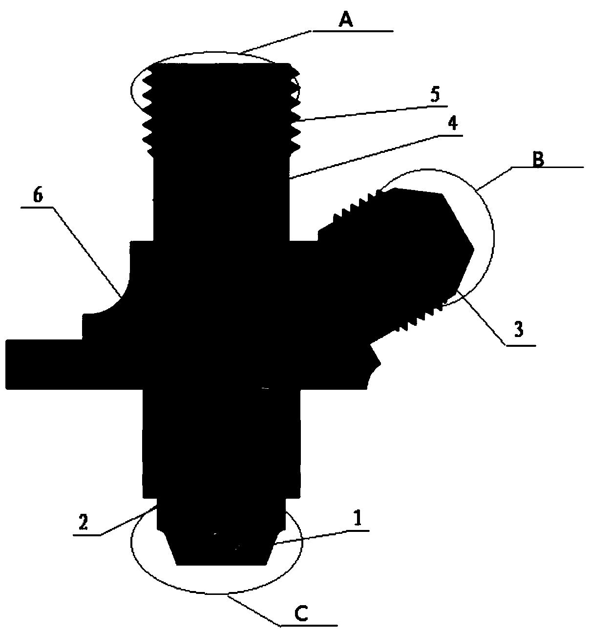
[0033] The aircraft engine nozzle such as figure 1 As shown, it consists of starting nozzle 1, nozzle body 2, throttle nozzle 3, oil filter 4, collar 5 and nozzle seat 6.

[0034] Use the starting nozzle flow tester (special for non-standard) to test the flow of the two engine nozzles respectively, the flow of the first nozzle is 5.4L / h, the flow of the second nozzle is 4.8L / h, the flow of the two nozzles The flow rate is close, and the carbon deposits are relatively serious, which cannot meet the requirements of aero-engines, and cannot continue to be used without removing the carbon deposits.

[0035] The first engine nozzle was cleaned with an ultrasonic cleaner for 1 hour, and then tested with a start-up nozzle flow tester. The flo...


PUM


Abstract

The invention discloses an aero-engine nozzle deposit carbon removing method which comprises the steps that a special tool is used for carrying out mechanical scraping on deposit carbon; a hydraulic tester is used for carrying out impact washing on nozzle deposit carbon; ultrasonic cleaning is carried out on the nozzle after impact washing; chemical washing is carried out on the nozzle after ultrasonic cleaning with a water solution with NaOH of 8-10g/L, Na3PO4 of 18-20g/L and Na5P3O10 of 27-30g/L; and ultrasonic cleaning is carried out again on the nozzle after chemical washing. According to the method, mechanical scraping, high-pressure oil impact, chemical washing and ultrasonic cleaning are combined, compared with a method only with ultrasonic cleaning, the average service life of the nozzle can be prolonged by 3-5 times, the rejection rate of engine nozzles is greatly lowered, and economical benefit is obvious.

Description

technical field [0001] The invention relates to an aero-engine, in particular to a method for removing carbon deposits on nozzles of an aero-engine. Background technique [0002] Existing aero-engine nozzle is an engine important part that is made of starting nozzle, nozzle body, throttle nozzle, oil filter, collar and nozzle seat, and the small spout of its starting nozzle head has swirl groove and small central hole. When the engine is working, due to insufficient combustion of the engine, coking and carbon deposits will be formed on the swirl groove, the center hole, the inner cavity wall of the nozzle and the oil filter. When the carbon deposit is serious, the nozzle will be blocked, and the nozzle flow rate will become smaller during performance testing. , or even zero, these directly affect the ignition of the igniter, and even cause aviation safety accidents. In order to ensure the stability of the engine operation, the flow performance of the nozzle must be tested a...

Claims


Application Information

Patent Timeline
Patent Type & Authority Applications(China)
IPC IPC(8): B08B7/04B08B1/00B08B3/08B08B3/12
CPCB08B1/005B08B3/08B08B3/12B08B7/04
Inventor 苑巍田文海付大为杨茜
Owner SHENYANG LIMING AERO-ENGINE GROUP CORPORATION
Why Eureka
Try Eureka