A metal vacuum melting die-casting forming equipment

A technology of die-casting and vacuum smelting, applied in the field of metal die-casting, which can solve the problems of high-quality die-casting equipment, easy-to-glow metal parts, and difficult-to-oxidize metal forming, so as to eliminate glow and discharge phenomena, reduce The effect of vacuuming time and low cost

Active Publication Date: 2016-02-24
DONGGUAN EONTEC CO LTD
View PDF6 Cites 1 Cited by
  • Summary
  • Abstract
  • Description
  • Claims
  • Application Information

AI Technical Summary

Problems solved by technology

[0002] With the development of industrial technology, it has become a common technology to use conventional die-casting equipment to melt and form components in the atmospheric environment. As the structure of the product becomes more and more complex, the performance and appearance requirements are also higher and higher. Forming components of forming equipment are prone to defects such as hard spots formed by oxidized slag inclusions during smelting and forming, and pores formed by gas involved in the molten metal; at the same time, some products are also lightweight and thin-walled. requirements, based on the above reasons, it is difficult for conventional die-casting equipment to complete high-quality
Moreover, conventional die-casting machines are smelted and die-casted in an atmospheric environment, and some easily oxidized metals whose properties are sensitive to oxygen content are even more powerless when smelted and die-casted.
[0003] In order to solve these problems, some vacuum die-casting equipment have also appeared in the industry. One way of these vacuum die-casting equipment is to vacuumize the temporarily closed cavity formed during injection from the mold side through high-precision control during injection molding. Although this method can reduce the defects of conventional die-casting equipment, it requires the equipment control system to respond quickly, the mold structure is relatively complex, the vacuum degree is low during injection, and the liquid metal is also in contact with the atmosphere, so it is not easy to form easily oxidized metals. ;Another way is to use one or several large sealed boxes to cover the melting and die-casting equipment. There are two methods: one method is to fill the inside of the sealed box with protective gas, such as nitrogen, argon etc., to prevent the oxidation of metal during smelting and forming, but it cannot solve the defect of air holes on the workpiece; another method is to vacuumize the sealed box, so that the melting and die-casting of metal materials are all in a vacuum environment Although this method can effectively solve the processing of forming defects and metal anti-oxidation, it concentrates smelting and die-casting in one or several sealed boxes, so not only the structure is more complicated, but also the sealing requirements of the structure are relatively high.
Due to the need for smelting in the box, considering the problem of efficiency, the introduction of high-frequency electrodes is generally used for induction heating, which will make the overall structure more complicated, and in a vacuum environment, the metal parts between the electrodes and the electrodes and their accessories are easily Glow phenomenon occurs, and in serious cases, discharge phenomenon will also occur, which will also cause unreasonable consumption and waste of electric energy and hidden safety hazards

Method used


Image

  • A metal vacuum melting die-casting forming equipment
  • A metal vacuum melting die-casting forming equipment
  • A metal vacuum melting die-casting forming equipment

Examples


Embodiment Construction

[0016] The present invention will be described in detail below in conjunction with the accompanying drawings and specific embodiments.

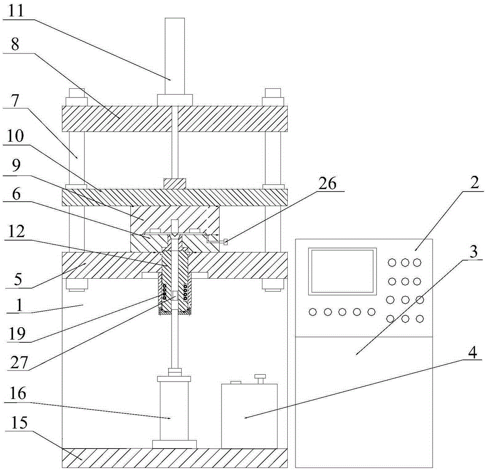
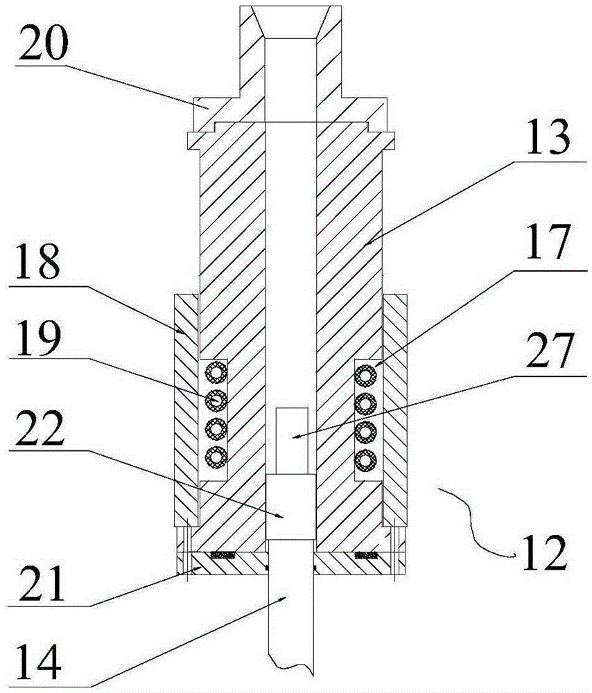
[0017] A metal vacuum melting die-casting molding equipment, such as figure 1 and figure 2 As shown, it includes a base 1 of the die-casting molding equipment, and a control system 2, a hydraulic system 3, and a vacuum system 4 of the die-casting molding equipment. , the four corners of the upper shelf plate 5 are connected to an upper fixed plate 8 through four guide pillars 7; between the upper shelf plate 5 and the upper fixed plate 8, on the four guide pillars 7, a movable template 10 with a movable mold 9 is installed and The mold clamping oil cylinder 11 on the upper fixed plate 8 is driven and connected to form a mold forming mechanism; in the center of the cavity of the fixed mold 6, a shooting mechanism 12 penetrating the upper shelf plate 5 is fixed, and the injection mechanism 12 includes a shooting mechanism 12. Cylinder 13, th...


PUM


Abstract

The invention discloses metal vacuum smelting die-casting forming equipment, which comprises a base of the die-casting forming equipment, a control system, a hydraulic system and a vacuuming system of the die-casting forming equipment, the base is a frame structure, and the upper shelf plate of the base is installed and fixed A certain mold is connected to an upper fixed plate through four guide pillars at the four corners of the upper shelf plate; between the upper shelf plate and the upper fixed plate, on the four guide pillars, a movable template with a movable mold and a joint on the upper fixed plate are installed. The mold oil cylinder is driven and connected; in the center of the fixed mold cavity, a shooting mechanism that penetrates the upper frame plate is fixed. The injection mechanism includes a injection cylinder, and the lower end of the injection cylinder is connected to a lower frame installed on the base through the injection rod. The injection cylinder on the board. In the present invention, the injection mechanism is arranged under the mold forming mechanism, and the lower section of the injection cylinder of the injection mechanism is set as a smelting chamber. By vacuuming the mold forming mechanism and the injection mechanism, heating and melting the metal, and then pushing the melt to the The cavity of the mold forming mechanism implements vacuum die-casting components.

Description

technical field [0001] The invention belongs to the technical field of metal die-casting, and relates to a metal die-casting device, in particular to a metal smelting die-casting device in a vacuum environment. Background technique [0002] With the development of industrial technology, it has become a common technology to use conventional die-casting equipment to melt and form components in the atmospheric environment. As the structure of the product becomes more and more complex, the performance and appearance requirements are also higher and higher. Forming components of forming equipment are prone to defects such as hard spots formed by oxidized slag inclusions during smelting and forming, and pores formed by gas involved in the molten metal; at the same time, some products are also lightweight and thin-walled. Requirements, based on the above reasons, it is difficult for conventional die-casting equipment to complete with high quality. Moreover, conventional die-castin...

Claims


Application Information

Patent Timeline
Patent Type & Authority Patents(China)
IPC IPC(8): B22D17/04B22D17/14B22D17/30
Inventor 汤铁装
Owner DONGGUAN EONTEC CO LTD
Why Eureka
Try Eureka