
Steel feeding platform of steel-pushing-type heating furnace

A heating furnace and steel platform technology, which is applied in the field of billet heating furnaces, can solve problems such as hidden dangers of safety, easy thermal deformation of the sliding table connecting plate, collision between the sliding table and the sliding table connecting plate, etc., and achieves strong applicability and long-term stability. Operation, reducing the effect of shutdown

Active Publication Date: 2014-03-19
SICHUAN DESHENG GRP VANADIUM & TITANIUM CO LTD
View PDF5 Cites 2 Cited by
  • Summary
  • Abstract
  • Description
  • Claims
  • Application Information

AI Technical Summary

Problems solved by technology

[0004] The technical problem to be solved and the technical task proposed by the present invention are to improve the existing technology and provide a pusher-type heating furnace steel feeding platform to solve the problem that the sliding table connecting plate of the heating furnace steel feeding platform in the current technology is easily deformed by heat. The steel billet is easy to collide with the sliding table and the connecting plate of the sliding table, which affects the production and causes safety hazards

Method used


Image

  • Steel feeding platform of steel-pushing-type heating furnace
  • Steel feeding platform of steel-pushing-type heating furnace
  • Steel feeding platform of steel-pushing-type heating furnace

Examples


Embodiment Construction

[0024] The technical solutions in the embodiments of the present invention will be clearly and completely described below. Obviously, the described embodiments are only some of the embodiments of the present invention, but not all of them. Based on the embodiments of the present invention, all other embodiments obtained by persons of ordinary skill in the art without making creative efforts belong to the protection scope of the present invention.

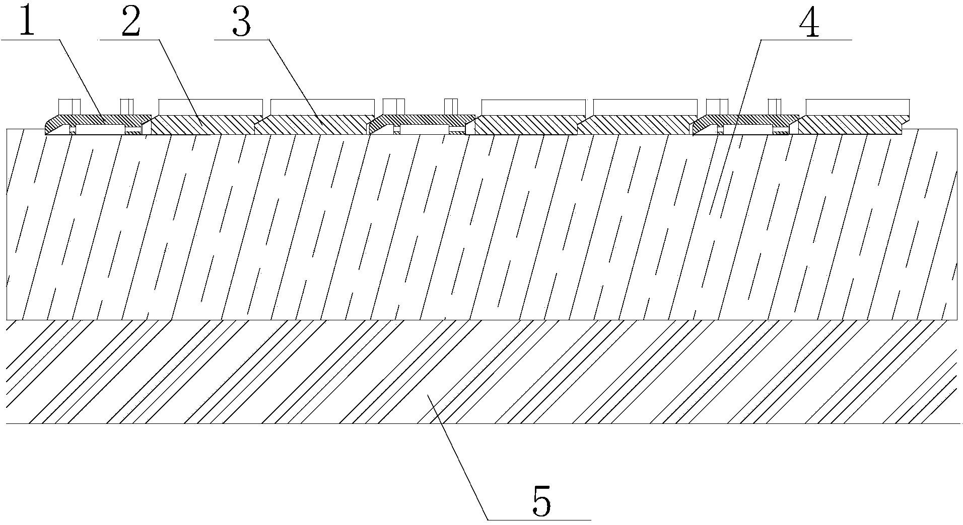
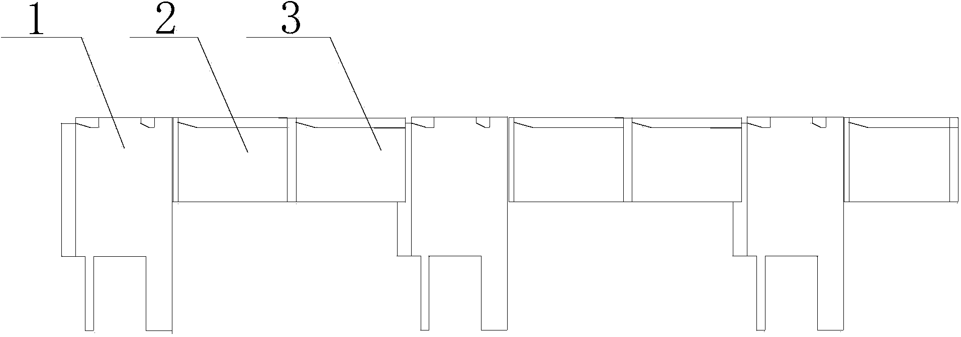
[0025] The embodiment of the invention discloses a steel-feeding platform for a pusher-type heating furnace, which reduces the area of ​​the connecting plate of the sliding table and increases its thickness. The impact is arched to ensure the smooth entry of the billet into the furnace.

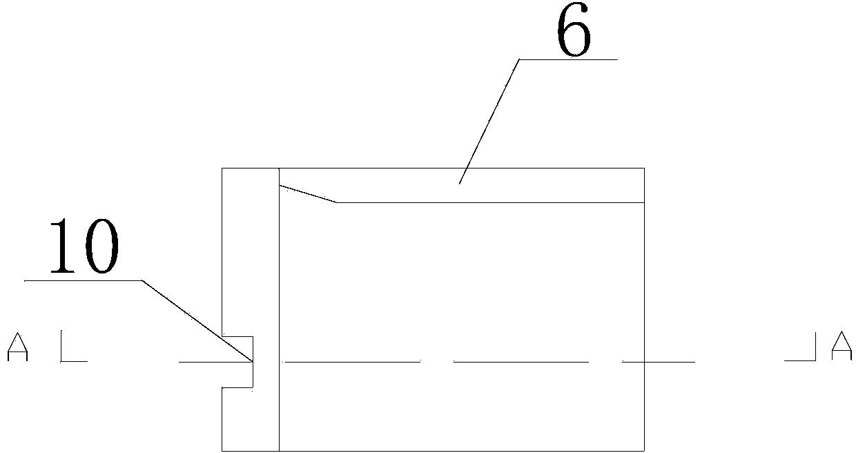
[0026] A steel feeding platform for a pusher type heating furnace, comprising a sliding table 1, a sliding table connecting plate I2 and a sliding table connecting plate II3, the left ends of the sliding table 1, the sliding table connecting plate ...


PUM


Abstract

The invention discloses a steel feeding platform of a steel-pushing-type heating furnace. The steel feeding platform of the steel-pushing-type heating furnace comprises sliding platforms, sliding platform connecting plates I and sliding platform connecting plates II. The steel feeding platform of the steel-pushing-type heating furnace is characterized in that the left ends of the sliding platforms, the sliding platform connecting plates I and the sliding platform connecting plates II are chamfered to form wedge-shaped heads, and the right ends of the sliding platforms, the sliding platform connecting plates I and the sliding platform connecting plates II are designed to form wedge-shaped grooves matched with the wedge-shaped heads; the slide platforms are connected with one another sequentially by the sliding platform connecting plates I and the sliding platform connecting plates II; the components are connected end to end by the match of the wedge-shaped heads and the wedge-shaped grooves and press against one other so as to form the steel feeding platform of the heating furnace. According to the steel feeding platform, the sliding platforms and the sliding platform connecting plates are connected in a pressing manner by the match of the wedge-shaped heads and the wedge-shaped grooves; an original sliding platform connecting plate is disassembled into two blocks with the length being half of the length of the original connecting plate, and meanwhile, the thickness is increased, so that the sliding platform connecting plates are free of deformation and arching because of high temperature, steel blanks can enter the furnace smoothly along the steel feeding platform, and the phenomenon of knocking the sliding platforms or the sliding platform connecting plates cannot be generated.

Description

technical field [0001] The invention relates to a billet heating furnace in the metallurgical steel rolling industry, in particular to a steel feeding platform for a pusher type heating furnace. Background technique [0002] In the metallurgical industry, a heating furnace refers to an industrial furnace that heats metal to the temperature of rolling to forging, including continuous heating furnaces and chamber heating furnaces. Continuous heating furnaces include pusher furnaces, walking furnaces, rotary hearth furnaces, compartmental furnaces and other continuous heating furnaces. Most of the continuous heating furnaces are used to heat metal blanks before rolling, and a few are used for forging and heat treatment. The pusher type continuous heating furnace is a continuous heating furnace that relies on a pusher to complete the task of transporting materials in the furnace. The billet slides on the bottom of the furnace or on slide rails supported by water-cooled pipes. I...

Claims


Application Information

Patent Timeline
IPC IPC(8): C21D9/70F27D3/02
Inventor 罗新生彭方明罗清明杨碧英宋德安
Owner SICHUAN DESHENG GRP VANADIUM & TITANIUM CO LTD
Learn More