Cabin roof splicing structure of prefabricated cabin and combined prefabricated cabin using same

A prefabricated cabin and cabin roof technology, applied in the field of prefabricated cabins, can solve the problems of large structural stress and easy deformation of the top, so as to improve reliability, ensure overall strength and bending and deformation resistance, and ensure reliability.

Active Publication Date: 2014-03-19
XUJI GRP +1
View PDF5 Cites 7 Cited by
  • Summary
  • Abstract
  • Description
  • Claims
  • Application Information

AI Technical Summary

Problems solved by technology

[0003] The prefabricated cabin of secondary equipment has high requirements on appearance, strength, rigidity, sealing and heat preservation, etc. In order to save internal space and improve utilization rate, it is now necessary to provide a combined cabin type composed of double cabins Prefabricated cabins, and no columns are allowed between the two cabins. After the prefabricated cabins of this structure are subjected to impact force during transportation and hoisting, the structure will be stressed, and the load-bearing beams on the span of 12 meters must be very high. strength, and when this prefabricated cabin is subjected to external forces such as strong winds and snowstorms during use, the top is very prone to deformation.

Method used


Image

  • Cabin roof splicing structure of prefabricated cabin and combined prefabricated cabin using same
  • Cabin roof splicing structure of prefabricated cabin and combined prefabricated cabin using same
  • Cabin roof splicing structure of prefabricated cabin and combined prefabricated cabin using same

Examples


Embodiment Construction

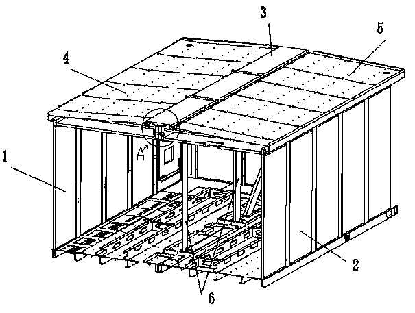
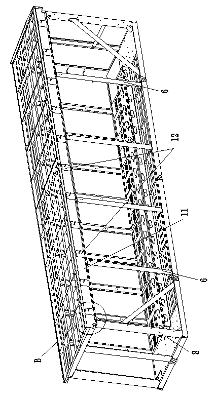
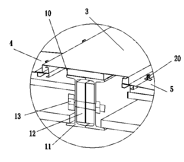
[0020] Figure 1-Figure 4 Shown is an embodiment of the combined cabin type prefabricated cabin of the present invention. In this embodiment, the prefabricated cabin is formed by docking the left cabin body 1 and the right cabin body 2. The frame, the bilge frame and the support column supported between the roof frame and the bilge frame are composed of butt beams at the joints of the roof frame and the bilge frame, and the left and right cabins are fastened by fastening bolts. The tank top butt beam and the two tank bottom butt beams are fixedly connected to realize merging to form a complete prefabricated cabin. Among them, the butt joint beam of the cabin roof is the load-bearing beam 11 along the length direction of the cabin body, and the I-shaped steel structure is adopted to meet its strength requirements. The upper and lower wings on the docking side form a hollow cavity, and a support piece whose thickness matches the distance between the two webs is fixed inside the...


PUM


Abstract

The invention relates to a combined prefabricated cabin and a cabin roof splicing structure of the prefabricated cabin. The cabin roof splicing structure of the prefabricated cabin comprises a left cabin roof and a right cabin roof which are joint in a butted mode, I-steel bearing beams extending in the length direction of a cabin body are arranged at the butt joint positions of two cabin roof frameworks, upper wing plates and lower wing plates of the two bearing beams are respectively joint in a butted mode, webs of the two bearing beams are connected and fixed together through fastening bolts arranged in the length direction of the webs at intervals, and a supporting piece with the thickness matched with the distance between the two webs is fixedly arranged between the webs of the two bearing beams. Because I-steel is adopted as the bearing beams at the butt joint positions of the two cabin roofs and the bearing beams are fixedly connected together through the fastening bolts mounted on the webs of the bearing beams, the overall strength and the bending and deformation resistance of the cabin roofs can be guaranteed; because the supporting piece between the two webs plays a role in auxiliary positioning and auxiliary supporting in the butt joint process of the I-steel bearing beams, not only is butt joint installation facilitated, but also it can be guaranteed that the bolt connection can meet a high pre-tightening force requirement, and thus the reliability, the tightness and the rigidity of connection of the two bearing beams are improved.

Description

technical field [0001] The invention relates to a prefabricated cabin. Background technique [0002] The prefabricated cabin is an emerging modular house similar to a container. It has also been widely used in the construction of substations in the power industry because of its detachable and mobile characteristics. The prefabricated cabin of the secondary equipment is an important part of the standard distribution substation. As the carrier of the secondary equipment of the substation, the secondary equipment of the substation enters the cabin and completes the integrated debugging before leaving the factory. The construction period of the substation is shortened and the investment cost is reduced. [0003] The prefabricated cabin of secondary equipment has high requirements on appearance, strength, rigidity, sealing and heat preservation, etc. In order to save internal space and improve utilization rate, it is now necessary to provide a combined cabin type composed of dou...

Claims


Application Information

Patent Timeline
Patent Type & Authority Applications(China)
IPC IPC(8): E04H5/04E04B1/58
Inventor 黄平丁丽平韩付申丁妍妍张永峰郭炎杰严华田改侠窦辉王卫红
Owner XUJI GRP
Why Eureka
Try Eureka