Hydraulic support used for roadway temporary support and erecting and use method of hydraulic support

A hydraulic support and temporary support technology, which is applied in mine roof support, mining equipment, earthwork drilling and mining, etc., can solve the problems of insufficient distance to the roof, easily damaged roof, high labor intensity, etc., and achieve a safe working environment for employees Reliable, improved engineering quality, high degree of automation effect

Active Publication Date: 2014-03-19
徐州莱柯斯特矿山工程技术有限公司 +1
View PDF6 Cites 16 Cited by
  • Summary
  • Abstract
  • Description
  • Claims
  • Application Information

AI Technical Summary

Problems solved by technology

[0011] 1. The traditional temporary support requires manual laying and top-connecting of roofing materials when running forward, which is labor-intensive and unsafe to work under an empty roof. It has almost no support for the roof and can only play a limited role in protecting the workers. , it often appears that the on-site operators try to save trouble, are afraid of trouble, and do not use it
[0012] 2. The joist-type temporary support of the roadheader frame is still under the empty roof, and the support area cannot reach the full section. The strength of the frame and the connection strength with the roadheader are limited, and the support force is very small. The roadheader cannot work in parallel during support and permanent support
Since the birth of the first-generation bolter in the 1960s, two changes have been made. The third generation of bolt-digging is integrated. Although the parallel operation of bolt-digging has been realized, the empty head distance of the bolt is large, generally more than 1.2-1.5 meters. , the support cannot keep up with the head, so it is only suitable for large-section rectangular or trapezoidal roadways with small mining depth, small mine pressure and good surrounding rock conditions. Therefore, it has not

Method used


Image

  • Hydraulic support used for roadway temporary support and erecting and use method of hydraulic support
  • Hydraulic support used for roadway temporary support and erecting and use method of hydraulic support
  • Hydraulic support used for roadway temporary support and erecting and use method of hydraulic support

Examples


Embodiment Construction

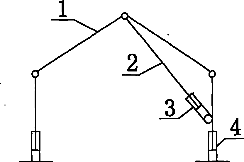
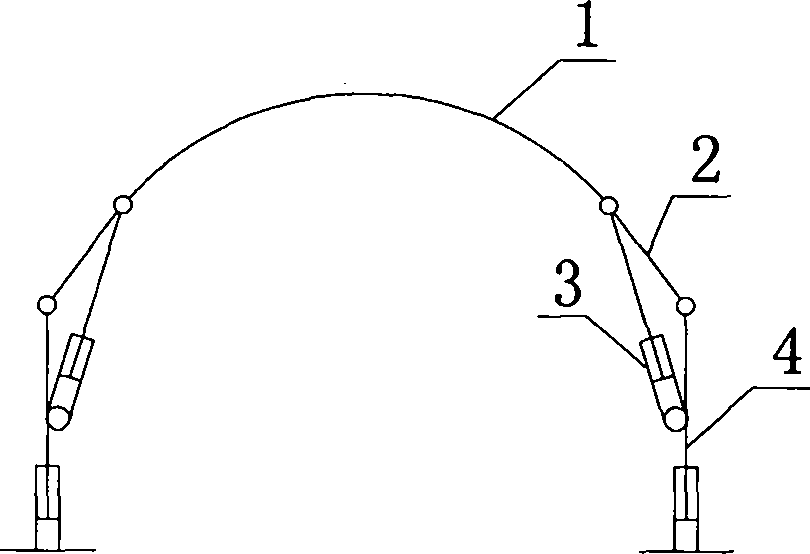
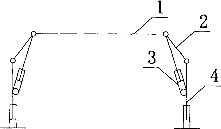
[0044] The hydraulic support mainly includes a top beam (1), an angle beam (2), a telescopic side support (4), and an ultra-statically indefinite balance oil cylinder (3); the top beam and the angle beam, and the angle beam and the telescopic support are hinged , One end of the super-static balance cylinder is hinged on the telescopic side support, and the other end is hinged on the top beam. Both the telescopic side support and the super-static balance cylinder are retractable, so as to realize the lifting and folding of the hydraulic support.

[0045] The super-static balance oil cylinder (3) is equipped with a two-way valve that communicates and closes on both sides. help body.

[0046] The telescoping side support (4) can be any kind of mode that can realize this support up and down stretching including hydraulic oil cylinder, telescoping wall etc.

[0047] According to the form of the roadway, the shape of the top beam of the hydraulic support is adapted to the top secti...


PUM


Abstract

The invention relates to a hydraulic support used for roadway temporary support and an erecting and use method of the hydraulic support. The hydraulic support comprises a top beam, an angle beam, a telescopic side support and an indeterminate balance oil cylinder. The support is erected at the front end of a temporary support area, always supports surrounding rocks extending to the rear end of the temporary support area after being erected like a band plate of a track which is static relative to the ground, then is folded and retracts from the rear end of the temporary support area, and moves to the front end of the temporary support area through an auxiliary facility so as to be erected and recycled. The support is simple in structure and strong in adaptability and improves drivaging efficiency.

Description

technical field [0001] The invention relates to a hydraulic support for underground engineering temporary support and its erection and use method; in particular, it is used for the temporary support of head-on excavation or the reinforced support of the advanced support pressure zone of the coal mining face. Background technique [0002] Support is required after the excavation of the underground project. In order to protect the surrounding rock from falling and collapsing during the support operation, temporary support must be provided first so that the operators can work under reliable support. [0003] There are mainly 6 types of temporary support methods for existing excavation roadways: [0004] 1. The traditional temporary support methods include suspension rings, steel pipes (or rails, section steel), etc., through the front channeling steel pipes, etc., plus roof protection materials, and single pillars with roof beams. [0005] 2. Rack-mounted joist roof protection...

Claims


Application Information

Patent Timeline
IPC IPC(8): E21D23/04E21D23/16
Inventor 郑东风周斌翟明华蒋宇静马丕良
Owner 徐州莱柯斯特矿山工程技术有限公司
Why Eureka
Try Eureka