
Refrigeration control system and method for data center

A data center cooling and control system technology, applied in the computer field, can solve the problems of wasted cooling energy consumption, excessive cooling, and inaccurate control parameters, and achieve the effects of avoiding over-cooling, saving labor costs, and improving operation and maintenance efficiency.

Active Publication Date: 2014-03-19
BEIJING BAIDU NETCOM SCI & TECH CO LTD
View PDF3 Cites 39 Cited by
  • Summary
  • Abstract
  • Description
  • Claims
  • Application Information

AI Technical Summary

Problems solved by technology

However, due to the influence of various factors, such as the specific layout of the computer room, the actual power consumption of the server, or the location of the server, the temperature inside the data center is not uniform.
Therefore, only a limited number of temperature sensors in the prior art cannot accurately reflect the internal temperature distribution of the data center, that is to say, the use of a limited number of temperature sensors cannot accurately reflect the fluctuation and change of the internal temperature of the data center
Therefore, when these temperature information is used as the control parameters of the cooling system, it is easy to cause over-cooling due to over-cautious cooling control strategy, resulting in waste of cooling energy consumption; The temperature in a local location is too high, which increases the probability of some servers malfunctioning due to high temperature
In addition, because the control parameters of the refrigeration system used are not precise enough, administrators often need to rely on manual experience to adjust the refrigeration control strategy
Therefore, not only the labor cost is wasted, but also the operation and maintenance efficiency of the refrigeration system is low
Furthermore, the existing cooling system and cooling control strategy are not suitable for the high-efficiency operation needs of larger and more complex data centers in the future

Method used


Image

  • Refrigeration control system and method for data center
  • Refrigeration control system and method for data center
  • Refrigeration control system and method for data center

Examples


Embodiment Construction

[0018] Embodiments of the present invention are described in detail below, examples of which are shown in the drawings, wherein the same or similar reference numerals designate the same or similar elements or elements having the same or similar functions throughout. The embodiments described below by referring to the figures are exemplary only for explaining the present invention and should not be construed as limiting the present invention. On the contrary, the embodiments of the present invention include all changes, modifications and equivalents coming within the spirit and scope of the appended claims.

[0019] In the description of the present invention, it should be understood that the terms "first", "second" and so on are used for descriptive purposes only, and cannot be interpreted as indicating or implying relative importance. In the description of the present invention, it should be noted that unless otherwise specified and limited, the terms "connected" and "connect...


PUM


Abstract

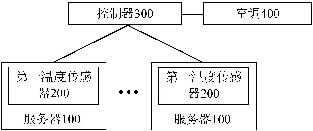
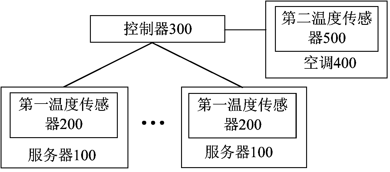
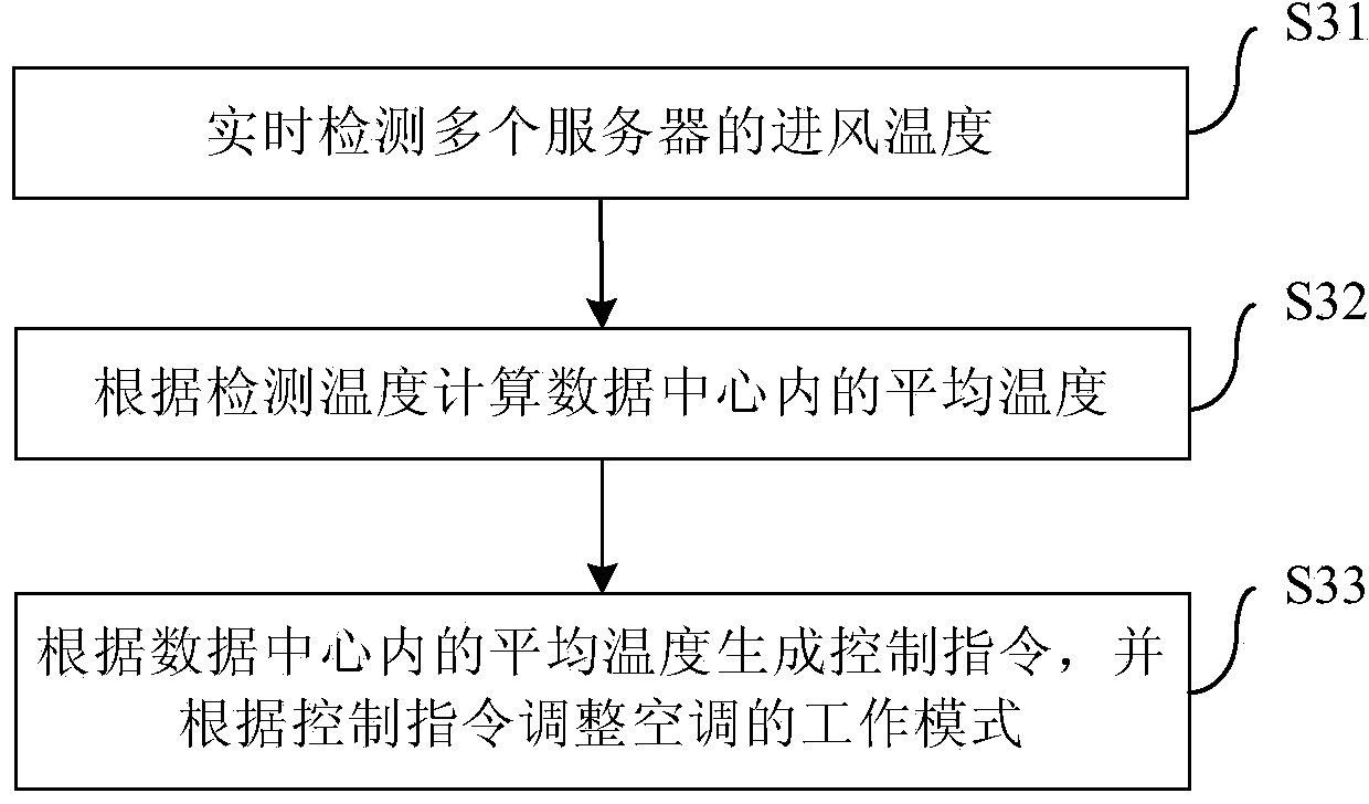
The invention provides a refrigeration control system and method for a data center. The system comprises a plurality of servers, a plurality of first temperature sensors, a controller and an air conditioner, wherein the plurality of first temperature sensors are mounted at air inlets of the plurality of servers and used for detecting air inlet temperatures of the plurality of servers in real time; the controller is used for receiving the detection temperatures sent by the plurality of first temperature sensors, calculating an average temperature in a data center according to the detection temperatures, and generating a control command according to the average temperature in the data center; and the air conditioner is sued for receiving the control command sent by the controller, and adjusting the working mode according to the control command. According to the system provided by the embodiment of the invention, on the premise that the cooling requirement safety of the servers is met, excessive refrigeration caused by an excessively cautious refrigeration control strategy as well as overheating of local servers caused by an excessively radical refrigeration control strategy can be avoided, and the refrigeration energy consumption and service failure rate are reduced greatly.

Description

technical field [0001] The present invention relates to the field of computer technology, in particular to a control system and method for refrigeration of a data center. Background technique [0002] The purpose of data center construction is to provide a good operating environment for the servers stored in the data center. Specifically, from the perspective of ensuring the reliability of the temperature of the server, the cooling system of the data center is to meet the heat dissipation requirements of the server. An indicator of the reliability of the server temperature. Therefore, the goal of the cooling system design in the data center is to ensure that the temperature of the cold aisle in the data center can be stabilized within a certain range, and the air supply volume can reach a certain index. [0003] At present, the data center refrigeration system usually detects the temperature in the data center through a limited number of temperature sensors installed at th...

Claims


Application Information

Patent Timeline
IPC IPC(8): F24F11/02
CPCF24F11/30F24F2110/10F24F2140/60H05K7/20836G05B2219/2614F24F11/77F24F11/84F24F11/46F24F11/63F24F11/38H05K7/20818
Inventor 张曙陈国锋丁瑞全
Owner BEIJING BAIDU NETCOM SCI & TECH CO LTD
Learn More