
Adjustment system

A technology of adjusting system and measuring system, applied in the field of adjusting system, can solve the problems of limited adjustment and high cost of adjustment technology, and achieve the effect of improving accuracy and low cost

Inactive Publication Date: 2014-03-19
MAUSER WERKE OBERNDORF MASCHENBAU
View PDF7 Cites 4 Cited by
  • Summary
  • Abstract
  • Description
  • Claims
  • Application Information

AI Technical Summary

Problems solved by technology

[0005] The disadvantage of this solution is that a high technical complexity is required to control the piezoelectric transducer
Furthermore, in such piezoelectric transducers the regulation is limited

Method used


Image

  • Adjustment system

Examples


Embodiment Construction

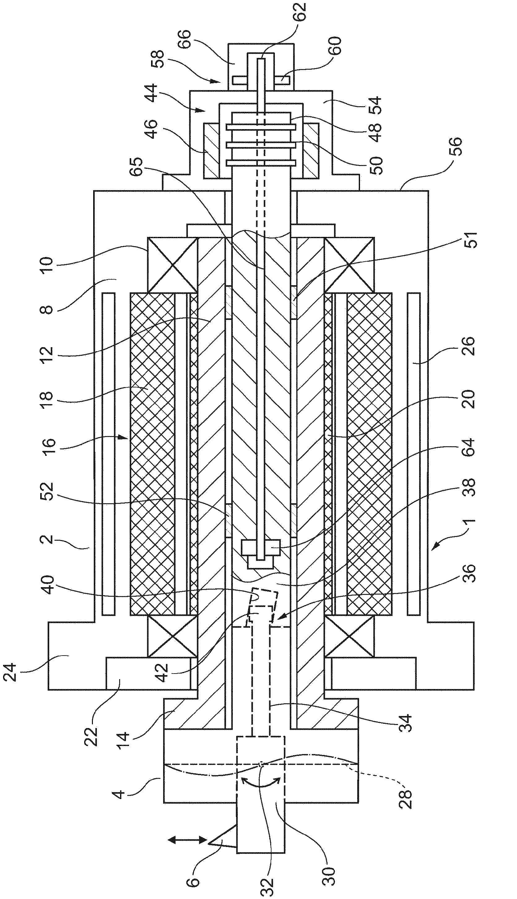
[0025] According to this longitudinal sectional view, the adjustment system 1 according to the invention consists in principle of a spindle 2 which carries a feed head, in the illustrated case a film tilt head 4, through which the tool edge 6 can be moved along By adjusting the direction, it is possible to precisely machine the geometric structures described at the beginning of this article, such as non-circular, elliptical holes of the workpiece or holes implemented in a flared shape along the hole axis, such as connecting rod eyelets. Obviously, instead of the film tilting head 4, other feed heads, such as a parallelogram head, can also be used, which can adjust the position of the cutting edge during processing.

[0026] The spindle 2 has a spindle housing 8 fixed on the machine tool or processing unit. The main shaft body 12 is rotatably supported in the main shaft housing 8 via a bearing device 10. The film tilting head 4 is clamped on the flange 14 projecting from the spin...


PUM


Abstract

Disclosed is an adjustment system comprising a feed head which supports a tool blade (6) and is mounted on a spindle (2). The tool blade is fed by an actuation element which can be moved by a contactless linear drive (44).

Description

Technical field [0001] The invention relates to an adjustment system according to the preamble of claim 1. Background technique [0002] Such adjustment systems are used, for example, for adjustment in the event of tool wear or during precision machining of the inner and outer contours of the workpiece, wherein these contours can be implemented cylindrically, eccentrically or non-circularly, for example. DE 10 2007 017 800A1 discloses an adjustment system in which the spindle carries a film tilting head, by means of which the cutting edge can be adjusted in the radial direction, so as to be circular, elliptical and / or along the piston The pin longitudinal axis is flared to form a small connecting rod eye. The adjustment of the film tilt head is carried out by a linearly adjustable operating element, which is also called a tie rod. The tool head that is connected to the film and carries the cutting edge can be tilted about the spindle axis through the tie rod to cause radial adju...

Claims


Application Information

Patent Timeline
Patent Type & Authority Applications(China)
IPC IPC(8): B23B29/034
CPCB23B29/034B23B29/03457B23B2260/0625B23B29/03446Y10T408/85Y10T408/85884Y10T408/85843B23Q17/2233B23Q15/22B23Q15/26B23B2260/102
Inventor 沃尔夫冈·伦普
Owner MAUSER WERKE OBERNDORF MASCHENBAU
Learn More