Locating device for machining piano iron plate locating hole and manufacturing method of locating device

A positioning device, positioning hole technology, applied in the direction of positioning measurement, metal processing equipment, manufacturing tools, etc. in the boring machine/drilling machine, can solve the design position deviation, the piano wire position deviation, the design datum and the processing datum do not coincide, etc. problem, to achieve the effect of convenient use and accurate location

Active Publication Date: 2014-03-26
PEARL RIVER PIANO GROUP
View PDF6 Cites 2 Cited by
  • Summary
  • Abstract
  • Description
  • Claims
  • Application Information

AI Technical Summary

Problems solved by technology

In the existing processing method, when processing the positioning hole 2, the side surface of the iron plate 1 is used as the processing reference plane in the left-right direction, and the upper side of the iron plate 1 is used as the processing reference plane in the up-down direction. The design basis is the side and the string nut, the design basis and the processing basis do not coincide; and during the casting process, the sand mold is prone to casting defects such as sand swelling and sand loss, resulting in a deviation between the actual position of the side of the iron plate 1 and the design position, and then After processing the positioning hole 2 using this side as a reference, the installed hole 1-2 of the final processed peg pin deviates from the ideal position, causing the deviation of the position of the piano wire, which makes the piano prone to action and reinforcement during installation. Ribs 1-4 interfere with each other, resulting in the failure of the piano to be assembled; and it is also easy to cause changes in the striking position, which increases the difficulty of debugging

Method used


Image

  • Locating device for machining piano iron plate locating hole and manufacturing method of locating device
  • Locating device for machining piano iron plate locating hole and manufacturing method of locating device
  • Locating device for machining piano iron plate locating hole and manufacturing method of locating device

Examples


Embodiment Construction

[0029] The present invention will be further described in detail below in conjunction with the embodiments and the accompanying drawings, but the embodiments of the present invention are not limited thereto.

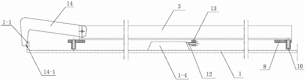
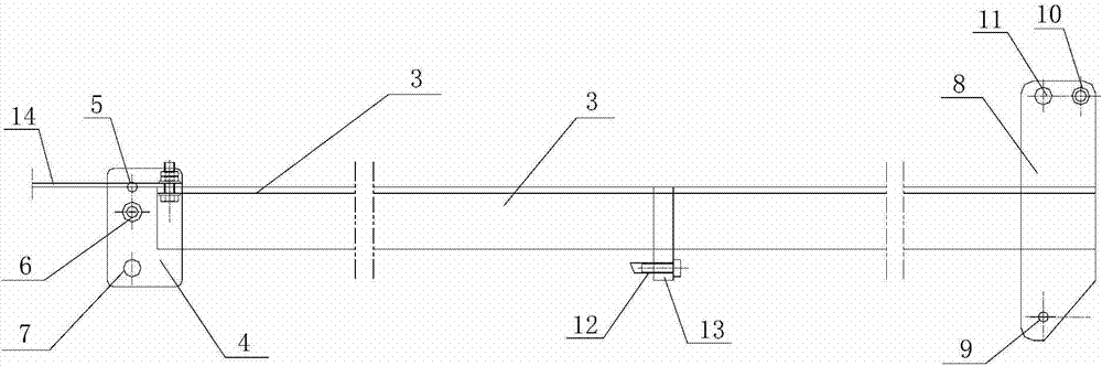
[0030] see Figure 2 to Figure 5 , the positioning device for processing the positioning hole of the piano iron plate of the present invention includes an intermediate connecting rod 3, which is made of an angle steel (or other rigid rods) with a right-angled cross section, and the angle steel has a horizontal portion and vertical part ( Figure 4 status shown). The two ends of described intermediate connecting rod 3 are respectively provided with a positioning guide plate, and each positioning guide plate is provided with longitudinal positioning member and drilling guide sleeve, wherein, the left positioning guide plate 4, which is positioned at the left end of intermediate connecting rod 3, The left longitudinal positioning part 5 and the left drilling guide sleeve ...


PUM


Abstract

The invention discloses a locating device for machining a piano iron plate locating hole and a manufacturing method of the locating device. The locating device comprises a middle connecting rod, the two ends of the middle connecting rod are respectively provided with a locating guiding plate, each locating guiding plate is provided with a longitudinal locating piece and a hole drilling guide sleeve, and the lower end of each longitudinal locating piece is provided with a V type notch matched with the surface of a chord pillow; the middle of the middle connecting rod is provided with a transverse locating piece, and one end of the middle connecting rod is further connected with a hook latch in a rotatable mode; the hook latch and the transverse locating piece are located on the two sides of an iron plate respectively. According to the locating device, the lateral side of a reinforcing rib is used as a datum point, the position accuracy of the locating hole can be guaranteed, finally-machined installation holes equivalently use the lateral side of the reinforcing rib as the datum point, the position relation between each installation hole and the chord pillow can be accordingly guaranteed, and the phenomenon that part of the finally-machined installation holes has interference in the chord pillow is avoided.

Description

technical field [0001] The invention relates to processing equipment for piano parts, in particular to a positioning device for processing positioning holes of a piano iron plate and a manufacturing method thereof. Background technique [0002] see figure 1 , the piano iron plate 1 is an important part of the piano, which mainly plays the role of making the piano strings arranged according to the design requirements and maintaining tension for a long time without slack, so that the piano emits beautiful notes; the iron plate 1 is formed by sand casting The upper part of the iron plate 1 is densely covered with a plurality of peg holes 1-2 for setting the peg pins, and the upper middle part of the iron plate 1 is provided with a longitudinal The reinforcing ribs 1-4, wherein, the peg pins and strings corresponding to the bass are installed on the left side of the ribs 1-4, and the peg pins and strings corresponding to the middle and high notes are installed on the right side...

Claims


Application Information

Patent Timeline
IPC IPC(8): B23B49/00
CPCB23B49/00
Inventor 梁志和陈玉华廖志辉梁剑非
Owner PEARL RIVER PIANO GROUP
Why Eureka
Try Eureka