Welding smoke exhaust room

A technology of smoke room and smoke exhaust pipe, which is applied in the direction of welding accessories, smoke removal, supply/exhaust protective gas devices, etc., which can solve the problem of difficult smoke handling and achieve the effect of improving work efficiency

Inactive Publication Date: 2014-03-26
WUHU POWER TECH
View PDF5 Cites 8 Cited by
  • Summary
  • Abstract
  • Description
  • Claims
  • Application Information

AI Technical Summary

Problems solved by technology

[0003] The invention provides a welding smoke exhaust room that can automatically exhaust smoke. The exhaust fan in the smoke exhaust pipe is

Method used


Image

  • Welding smoke exhaust room

Examples


Embodiment Construction

[0010] In order to deepen the understanding of the present invention, the present invention will be further described below in conjunction with examples, which are only used to explain the present invention and do not constitute a limitation to the protection scope of the present invention.

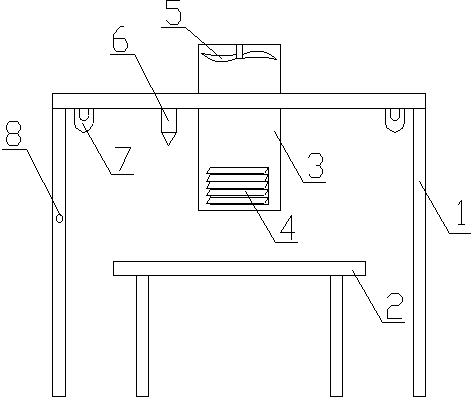
[0011] Such as figure 1 As shown, this embodiment provides a welding smoke exhaust room, including a room body 1, a welding workbench 2 is arranged in the middle of the room body 1, and a smoke exhaust pipe 3 is arranged above the welding workbench 2. The lower end of the smoke pipe 3 is provided with an arc shield 4 , and the top of the smoke exhaust pipe 3 is provided with an exhaust fan 5 . The house body 1 is provided with a smoke detector 6, and the smoke detector 6 controls the exhaust fan 5 to work. The four corners of the top of the room body 1 are provided with lighting lamps 7 for illuminating the welding workbench 2 , and a switch 8 is arranged outside the room body 1 to contr...


PUM


Abstract

The invention provides a welding smoke exhaust room comprising a house. A welding workbench is arranged in the middle of the house, an exhaust pipe is arranged above the welding workbench, arc baffles are arranged at the lower end of the exhaust pipe, and an exhaust fan is arranged at the top end of the exhaust pipe. Smoke generated on welding site can be exhausted out of the house rapidly by the exhaust pipe arranged above the welding workbench, so that working staff in the workshop is protected and work efficiency is improved.

Description

technical field [0001] The invention relates to a workshop, in particular to a welding smoke exhaust room capable of automatic smoke exhaust. Background technique [0002] Since the original carbon dioxide welding was only made and installed on the top of the suction hood or the axial flow fan was installed directly on the roof of the workshop, the exhaust effect was not good. In the face of the generated smoke and dust, fans can only blow it away, causing the smoke and dust in the workshop to be filled, which hurts the health of the production site workers. Therefore, it is particularly important to solve the problem that the smoke is not easy to handle during welding. Contents of the invention [0003] The invention provides a welding smoke exhaust room capable of automatically exhausting smoke. The exhaust fan in the smoke exhaust pipe is used to exhaust the smoke from the room together with the air, which solves the problem that the smoke is difficult to handle during...

Claims


Application Information

Patent Timeline
IPC IPC(8): B23K9/32B23Q37/00B08B15/04
CPCB23K9/325B23K9/32
Inventor 陈昊吴云晴张俊霞章慷童平吴小毛陈一田
Owner WUHU POWER TECH
Why Eureka
Try Eureka