Clamp

A fixture and top-tightening technology, applied in the field of machinery, can solve the problems of high risk, difficult to control welding quality, and low efficiency of manual welding.

Active Publication Date: 2014-03-26
DATONG ELECTRIC LOCOMOTIVE OF NCR
View PDF4 Cites 8 Cited by
  • Summary
  • Abstract
  • Description
  • Claims
  • Application Information

AI Technical Summary

Problems solved by technology

[0003] In the prior art, the end beams are generally welded by hand, the efficiency of manual welding is low, and the welding quality is difficult to control. The existing manipulator can be used for automatic welding, but there is n

Method used


Image

  • Clamp
  • Clamp
  • Clamp

Examples


Embodiment Construction

[0027] Before introducing the technical solution of the embodiment of the present invention, the structure of the end beam will be introduced in detail.

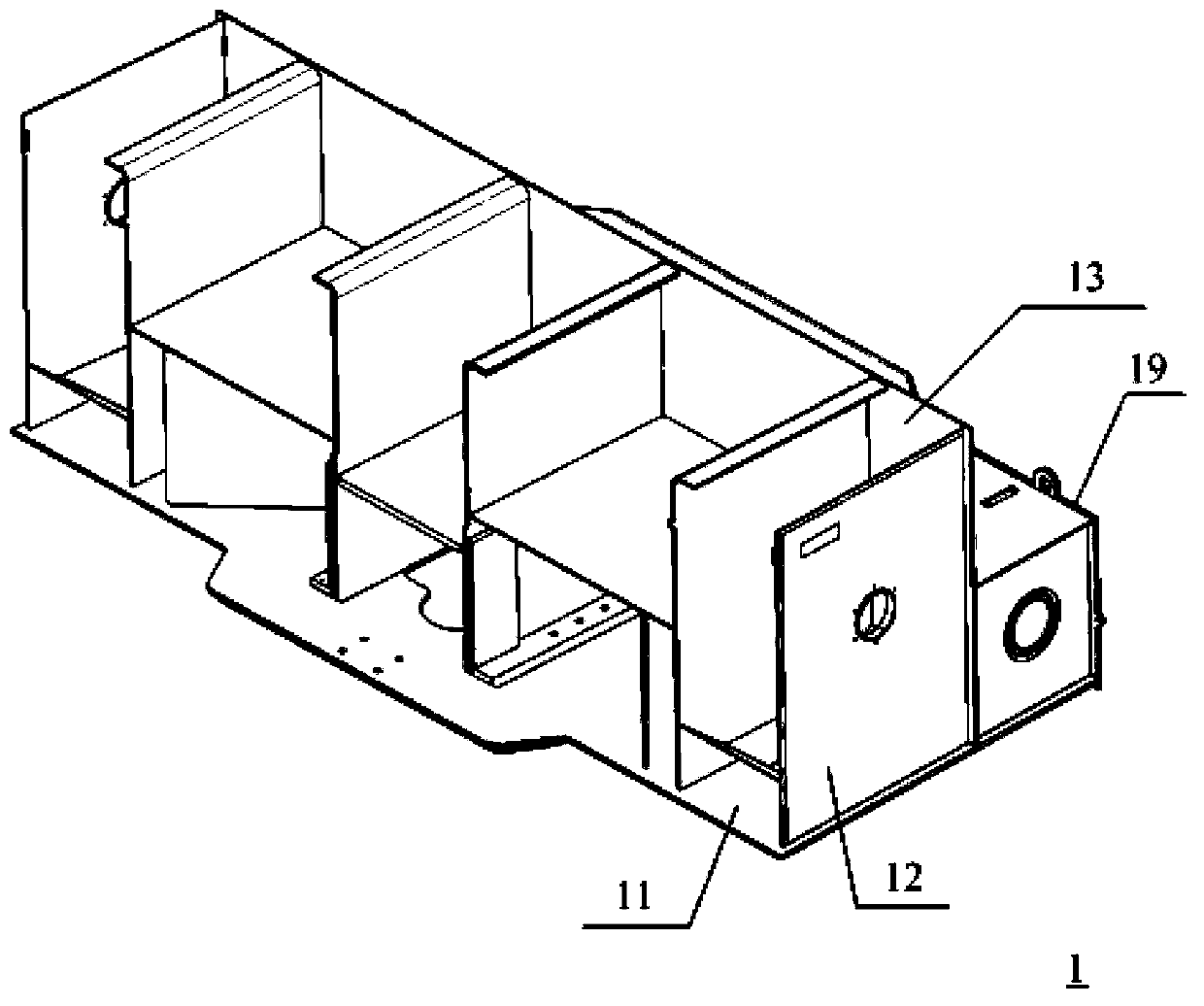
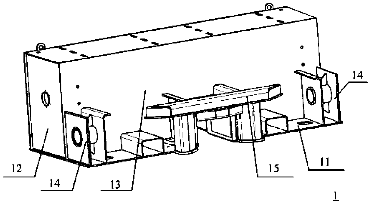
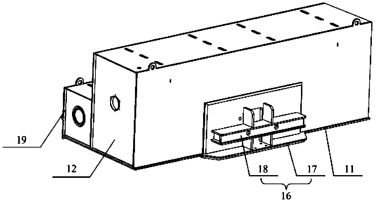
[0028] Figure 1a is the three-dimensional schematic diagram of the end beam, Figure 1b Stereoscopic representation of the end beam Figure II , Figure 1c Stereoscopic representation of the end beam Figure three .

[0029] see Figure 1a-Figure 1c , The end beam 1 includes a base plate 11 , two side plates 12 , a coupler box cluster plate 13 , two suspension seats 14 and a bent plate 15 . The base plate 11 is rectangular, the side plates 12 are fixed on both ends of the base plate 11 , and the coupler box cluster plate 13 is fixed on the base plate 11 and is located between the two side plates 12 . see Figure 1b , The coupler box cluster plate 13 has an inner cavity. Hanger composition 14 is symmetrically fixed on the edge of base plate 11, and leans against on the coupler box cluster plate 13. see Figure 1b , ...


PUM


Abstract

The invention discloses a clamp. The clamp comprises a supporting component, first abutting components, second abutting components and third abutting components, wherein the supporting component is used for providing supporting, the first abutting components are fixed to the supporting component, and are used for being in cooperation in the vertical direction to clamp an end beam which is processed through spot welding, the second abutting components are fixed to the supporting component, and are used for being in cooperation in the left-and-right direction to clamp the end beam, and the third abutting components are fixed to the supporting component, and are used for being in cooperation in the front-and-rear direction to clamp the end beam. According to the technical scheme, the clamp acts on the positions, without weld joints, of the end beam, and can carry out locating on the end beam in six directions, all the weld joints on the end beam can be exposed, a mechanical arm does not need to continuously change positions to meet the requirement for welding, reliability of locating of the end beam is effectively ensured, the mechanical arm can be smoothly used for carrying out welding operation in the follow-up working procedures, and welding quality and welding efficiency can be ensured.

Description

technical field [0001] The invention relates to mechanical technology, in particular to a clamp. Background technique [0002] The end beam is an important part of the electric locomotive. Taking the HXD2B and HXD2C series electric locomotives as an example, the end beam is a box structure, and the end beam consists of a bottom plate, a cover plate, a coupler box cluster plate and a hanger. Assembly welding is used between the parts of the end beam, and the outer surface welds of the end beam are mostly long straight welds. [0003] In the prior art, the end beams are generally welded by hand, the efficiency of manual welding is low, and the welding quality is difficult to control. The existing manipulator can be used for automatic welding, but there is no fixture in the prior art, and the end beams can only be welded by hand. The method is fixed. When the end beam is fixed by hand, the risk of welding by manipulator is very high, and the personal safety of operators is d...

Claims


Application Information

Patent Timeline
IPC IPC(8): B23K37/04
CPCB23K37/0443
Inventor 韩思远于行飞
Owner DATONG ELECTRIC LOCOMOTIVE OF NCR
Why Eureka
Try Eureka