
Planar special-shaped non-circular grinding contouring control method

A contour control and special-shaped technology, applied in the direction of grinding automatic control device, grinding machine parts, grinding/polishing equipment, etc. The effect of convenience and algorithm versatility

Active Publication Date: 2014-03-26
SHANGHAI MACHINE TOOL WORK
View PDF5 Cites 15 Cited by
  • Summary
  • Abstract
  • Description
  • Claims
  • Application Information

AI Technical Summary

Problems solved by technology

[0003] At present, there are special analytical algorithms for special shapes such as crankshafts or cams, but for any special-shaped non-circular rotary parts on the grinding plane, the positions of C-X coordinate points are usually determined one by one by geometric drawing method, which is cumbersome and requires a lot of work.

Method used


Image

  • Planar special-shaped non-circular grinding contouring control method
  • Planar special-shaped non-circular grinding contouring control method
  • Planar special-shaped non-circular grinding contouring control method

Examples


Embodiment Construction

[0019] The present invention will be further described below in conjunction with the accompanying drawings and embodiments.

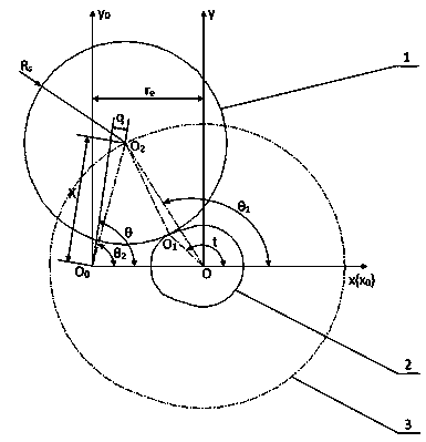
[0020] see figure 1 It is an example of any special-shaped application. The number 1 in the figure is the grinding wheel, the number 2 is the profile of the special shape, and the number 3 is the center of the grinding wheel obtained by the algorithm module. motion track.

[0021] For the convenience of understanding the technical scheme of the present invention, first make the principle derivation as follows:

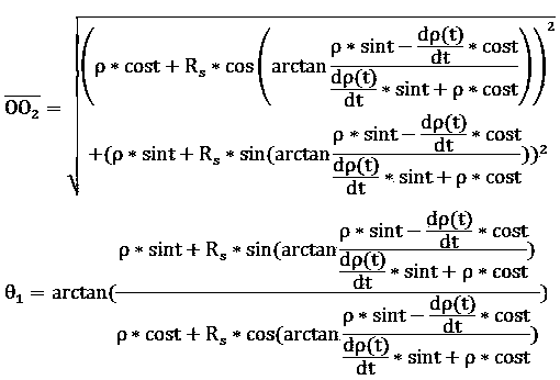
[0022]

[0023]

[0024]

[0025] In the formula is the coordinate system xOy (with the center of rotation of the profile is the origin of the coordinates) under any profile point Corresponding grinding wheel center position , After offsetting the coordinate system, in the coordinate system x 0 o 0 the y 0 (C-axis rotation center is the center position of the grinding wheel under the origin of the coordinate system); ...


PUM


Abstract

The invention relates to a planar special-shaped non-circular grinding contouring control method which includes the steps of (1) initializing parameters including rho, t, Rs, re and q; (2) finding a grinding wheel center position O2 and a grinding wheel center track rotation angle theta 1 by means of the formula, wherein the grinding wheel center position O2 and the grinding wheel center track rotation angle theta 1 correspond to any special-shaped contouring point O1 under a coordinate system xOy, and the coordinate system xOy takes the rotation center O of a special contouring as the coordinate origin; (3) shifting the coordinate system according to an eccentric distance re, and calculating the grinding wheel center displacement and a grinding wheel center track rotation angle theta 2 under a coordinate system x0O0y0, wherein the coordinate system x0O0y0 takes the rotation center O0 of a C-axis as the coordinate origin; (4) solving a grinding wheel center displacement X and a grinding wheel center track rotation angle theta with a center height difference q; (5) determining a C-X axis interpolation relation according to the obtained grinding wheel center track rotation angle theta and the grinding wheel center position X.

Description

technical field [0001] The invention relates to a method for controlling the contour of plane special-shaped non-circular grinding. Background technique [0002] The plane special-shaped non-circular contour can be expressed by a certain mathematical model, or it can be given by discrete point cloud data. Non-circular grinding generally refers to the grinding process in which the trajectory of the grinding point is a non-circular curve in the CNC grinding process. Usually, the tangent point tracking grinding technology of C-X axis synchronous grinding is adopted. The headstock of the grinding machine, that is, the C axis, drives the workpiece to rotate, and the grinding wheel frame, that is, the X axis, tracks the tangent point according to the command of the headstock. A technology for grinding. [0003] At present, there are special analytical algorithms for special shapes such as crankshafts or cams, but for any special-shaped non-circular rotary parts on the grinding pl...

Claims


Application Information

Patent Timeline
Patent Type & Authority Applications(China)
IPC IPC(8): B24B49/00B24B51/00
CPCB24B51/00
Inventor 肖蓉房小艳杨云梅
Owner SHANGHAI MACHINE TOOL WORK
Learn More