Full-automation filling machine

A filling machine, fully automatic technology, applied in the direction of packaging, transportation and packaging, packaging item types, etc., can solve the problems that affect the filling process, affect the filling action, and cannot guarantee the complete correspondence of the filling bottle, so as to ensure the filling The effect of device stability and accuracy, lower production cost, and higher production efficiency

Active Publication Date: 2014-03-26
CHENGDU WENJIANG HAIKE INSTR FACTORY
View PDF6 Cites 28 Cited by
  • Summary
  • Abstract
  • Description
  • Claims
  • Application Information

AI Technical Summary

Problems solved by technology

[0002] In the existing filling machine, the filling bottle is conveyed by the conveying mechanism. When the filling bottle is sent to the corresponding blanking station of the turntable, the material is sent to the corresponding filling bottle below by the blanking mechanism to realize filling. Therefore, during the filling process, the precise positioning of the filling bottle is very important. If the bottle mouth does not correspond to the corresponding lower hopper, the material cannot be filled into the filling bottle, thus affecting the normal filling action.
For the conveying of filled bottles, if the filled bottles are of irregular shape, the filled bottles will rotate freely on the conveyor belt due to their mutual extrusion during the conveying process, thus causing the filled bottles to be sent to At the filling station, it is impossible to ensure that the bottle opening of the filling bottle corresponds exactly to the lower hopper, thus affecting the normal filling process

Method used


Image

  • Full-automation filling machine
  • Full-automation filling machine
  • Full-automation filling machine

Examples


Embodiment 1

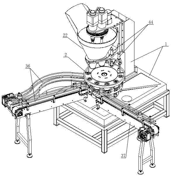
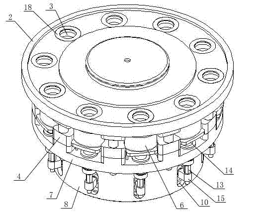
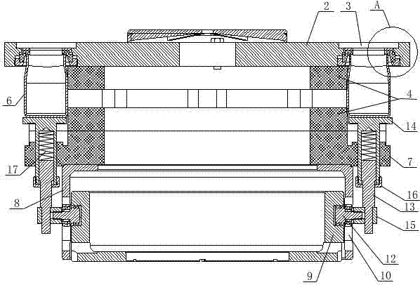
[0036] Embodiment 1: as Figure 1-5 As shown, a fully automatic filling machine includes a frame 1 and a discharge device arranged on the frame 1, a turntable device, a feeding device and a conveying device, and the turntable device includes a turntable 2 connected to a rotary drive mechanism And a number of blanking through holes 3 evenly distributed on the turntable 2, a bottle clamping plate 4 is arranged below the rotary plate 2, and a number of bottle clamping grooves corresponding to the blanking through holes 3 are arranged around the bottle clamping plate 4 5. The bottle clamping groove 5 is matched with the shape of the filling bottle 6, and the ejector pin fixing plate 7 is arranged under the bottle clamping plate 4, and the turntable 2, the bottle clamping plate 4 and the ejector pin fixing plate 7 are connected by The parts are connected as a whole. Below the ejector pin fixing plate 7, several bottle jacking mechanisms corresponding to the bottle clamping groove 5...

Embodiment 2

[0043] Embodiment 2: as Figure 13 As shown, a sealing plate 41 fixedly connected to the frame 1 is provided above the turntable 2, and a discharge hole corresponding to the blanking through hole 3 is provided on the sealing plate 41 corresponding to the blanking station. An adjustable measuring cup 42 is arranged above the sealing plate 41, and the adjustable measuring cup 42 is connected to the measuring cup turntable 43 above it, and a plurality of holes corresponding to the adjustable measuring cup 42 are arranged on the measuring cup turntable 43 , the discharge port of the discharge device communicates with the hole on the measuring cup turntable 43 correspondingly, and the lower end of the adjustable measuring cup 42 forms a relatively airtight gap with the sealing plate 41 when it is in the filling station and the bottle feeding and discharging station. The material-holding space, when it is at the material-discharging station, its lower end opening communicates with t...


PUM


Abstract

The invention discloses a full-automation filling machine which comprises a rack, a discharging device, a rotation plate device, a baiting device and a conveying device, wherein the discharging device, the rotation plate device, the baiting device and the conveying device are arranged on the rack. The rotation plate device comprises a rotation plate and multiple baiting through holes. A bottle clamping plate is arranged below the rotation plate, multiple bottle clamping grooves are formed in the periphery of the bottle clamping plate and a bottle ejecting mechanism is arranged below the ejector rod fixing plate. The discharging device is located above the rotation plate. A discharging opening of the discharging device is communicated with the baiting through holes in the rotation plate. The baiting device is located above the rotation plate and matched with the baiting through holes corresponding to baiting stations. The conveying device corresponds to the bottle clamping grooves at bottle inlet stations and bottle outlet stations. According to the full-automation filling machine, the bottle clamping plate is used for clamping and fixing filling bottles and a bottle jacking mechanism is used for jacking the corresponding filling bottle, so that the filling bottle totally corresponds to the corresponding baiting through hole of the rotation plate. In the whole filling process, the filling bottles can rotate synchronously along with the rotation plate and the filling problem due to the fact that the filling bottles do not align with a baiting hopper in an existing structure is solved.

Description

technical field [0001] The invention relates to a fully automatic filling machine. Background technique [0002] In the existing filling machine, the filling bottle is conveyed by the conveying mechanism. When the filling bottle is sent to the corresponding blanking station of the turntable, the material is sent to the corresponding filling bottle below by the blanking mechanism to realize filling. Therefore, during the filling process, the precise positioning of the filling bottle is very important. If the bottle mouth does not correspond to the corresponding lower hopper, the material cannot be filled into the filling bottle, thus affecting the normal filling action. . For the conveying of filled bottles, if the filled bottles are of irregular shape, the filled bottles will rotate freely on the conveyor belt due to their mutual extrusion during the conveying process, thus causing the filled bottles to be sent to At the filling station, it is impossible to ensure that the...

Claims


Application Information

Patent Timeline
Patent Type & Authority Applications(China)
IPC IPC(8): B65B1/12B65B1/04B65B43/42B65B1/36
Inventor 郑友林
Owner CHENGDU WENJIANG HAIKE INSTR FACTORY
Why Eureka
Try Eureka