
Underwater structure riprap foundation bed vibration compaction and vibration leveling device and construction method

A technology of riprap foundation bed and leveling device, which is applied in the direction of measuring device, infrastructure engineering, height/level measurement, etc., can solve the problems of short construction period, low cost, and low construction efficiency, and achieve low cost and low cost Effect

Inactive Publication Date: 2014-03-26
NO 2 ENG CO LTD OF CCCC FIRST HARBOR ENG
View PDF7 Cites 6 Cited by
  • Summary
  • Abstract
  • Description
  • Claims
  • Application Information

AI Technical Summary

Problems solved by technology

[0003] Introduction to bed compaction: Hammer ramming uses a heavy hammer to use a punching machine to achieve bed compaction. This method has a long construction period and high cost, and it is difficult to meet the requirements of rapid and large-area compaction. Explosive ramming has a short construction period, quick results, and low cost. The quality can also be guaranteed, but the seismic effect on the surrounding environment is obvious, so it is restricted by the surrounding environment; vibration compaction is a new method, which has a short construction period, low cost, low cost, and has little impact on the environment. development trend
[0004] Introduction to bed leveling methods: Underwater artificial leveling: low cost of manual leveling at one time, but high labor intensity, high safety risks, and low construction efficiency; frame leveling machine: backward feeding method and inaccurate feeding position , unable to realize automatic continuous operation; bottom-mounted leveling ship: limited by water depth; platform ship-type leveling ship: expensive; walking leveling machine: relatively harsh on construction conditions, and the scope of application is small

Method used


Image

  • Underwater structure riprap foundation bed vibration compaction and vibration leveling device and construction method

Examples


Embodiment Construction

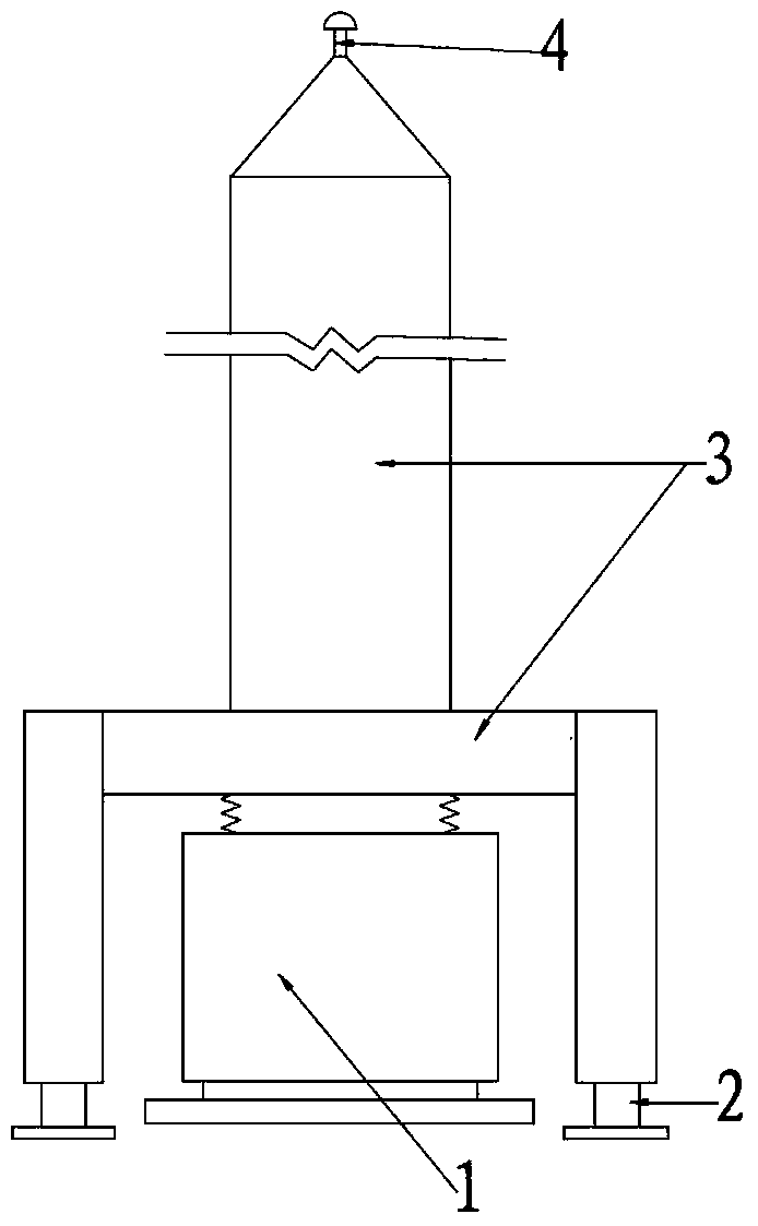
[0017] Such as figure 1 As shown, the vibration-dense, high-precision vibration leveling device of the underwater structure riprap foundation bed of the present invention includes a frame 3, and the frame 3 is provided with a hydraulic support device 2 controlled by a control system 4 for automatic attitude adjustment, A vibrating hammer 1 is arranged inside the frame 3, and the top of the frame 3 is exposed to the water surface. The top of the frame 3 is provided with a control system 4, and the control system 4 includes a GPS elevation and plane positioning measurement and control system.

[0018] As far as the construction method of using the vibration compacting and high-precision vibration leveling device of the riprap foundation bed of the underwater structure, the method includes the following steps,

[0019] (1) Display the location of the device and the elevation of the foundation bed in real time through the GPS elevation and plane positioning measurement and control...


PUM


Abstract

The invention relates to an underwater structure riprap foundation bed vibration compaction and vibration leveling device. A rack is provided with a system for automatically adjusting postures, a vibratory hammer is arranged in the rack, the top end of the rack is exposed out of the surface of water, and a GPS elevation plane positioning measurement and control system is arranged at the top end of the rack. A construction method includes the steps that first, the position of the device and the elevation of a foundation bed are displayed in real time through the GPS elevation plane positioning measurement and control system; second, the perpendicularity and the elevation of the device are controlled by the system for automatically adjusting the postures; third, through measurement and control of a sensor and the GPS elevation measurement and control system, when the underwater structure riprap foundation bed is vibrated and leveled to reach the pre-determined elevation through excitation force generated by the vibratory hammer, the vibratory hammer automatically stops. The underwater structure riprap foundation bed vibration compaction and vibration leveling device is low in cost, the vibration leveling accuracy reaches + / -5cm, the device adapts to deep water in open seas, and cost is low compared with a manual leveling device in shoal waters.

Description

technical field [0001] The invention relates to a vibration compacting and high-precision vibration leveling device and a construction method for a riprap foundation bed of an underwater structure. Background technique [0002] At present, the main methods of compacting the riprap foundation bed of underwater structures in China are: vibration compaction, hammer ramming, and explosive ramming; There are five types of flat boat, platform boat screed, and walking screed. [0003] Introduction to bed compaction: Hammer ramming uses a heavy hammer to use a punching machine to achieve bed compaction. This method has a long construction period and high cost, and it is difficult to meet the requirements of rapid and large-area compaction. Explosive ramming has a short construction period, quick results, and low cost. The quality can also be guaranteed, but the seismic effect on the surrounding environment is obvious, so it is restricted by the surrounding environment; vibratio...

Claims


Application Information

Patent Timeline
Patent Type & Authority Applications(China)
IPC IPC(8): E02D3/046E02F3/76G01C5/00
Inventor 刘德进曲俐俐杨瑞亮陆连洲王翔冯海暴李振国冯甲鑫
Owner NO 2 ENG CO LTD OF CCCC FIRST HARBOR ENG
Learn More