
System and method for controlling LPG pump and fuel supplying system of LPI engine

An engine and fuel technology, applied in the direction of engine components, engine control, combustion engine, etc., can solve problems such as poor filling, poor durability of LPG fuel pump 3, and poor engine performance, so as to prevent filling failure and suppress internal pressure and the effect of temperature rise

Inactive Publication Date: 2014-03-26
HYUNDAI MOTOR CO LTD
View PDF8 Cites 9 Cited by
  • Summary
  • Abstract
  • Description
  • Claims
  • Application Information

AI Technical Summary

Problems solved by technology

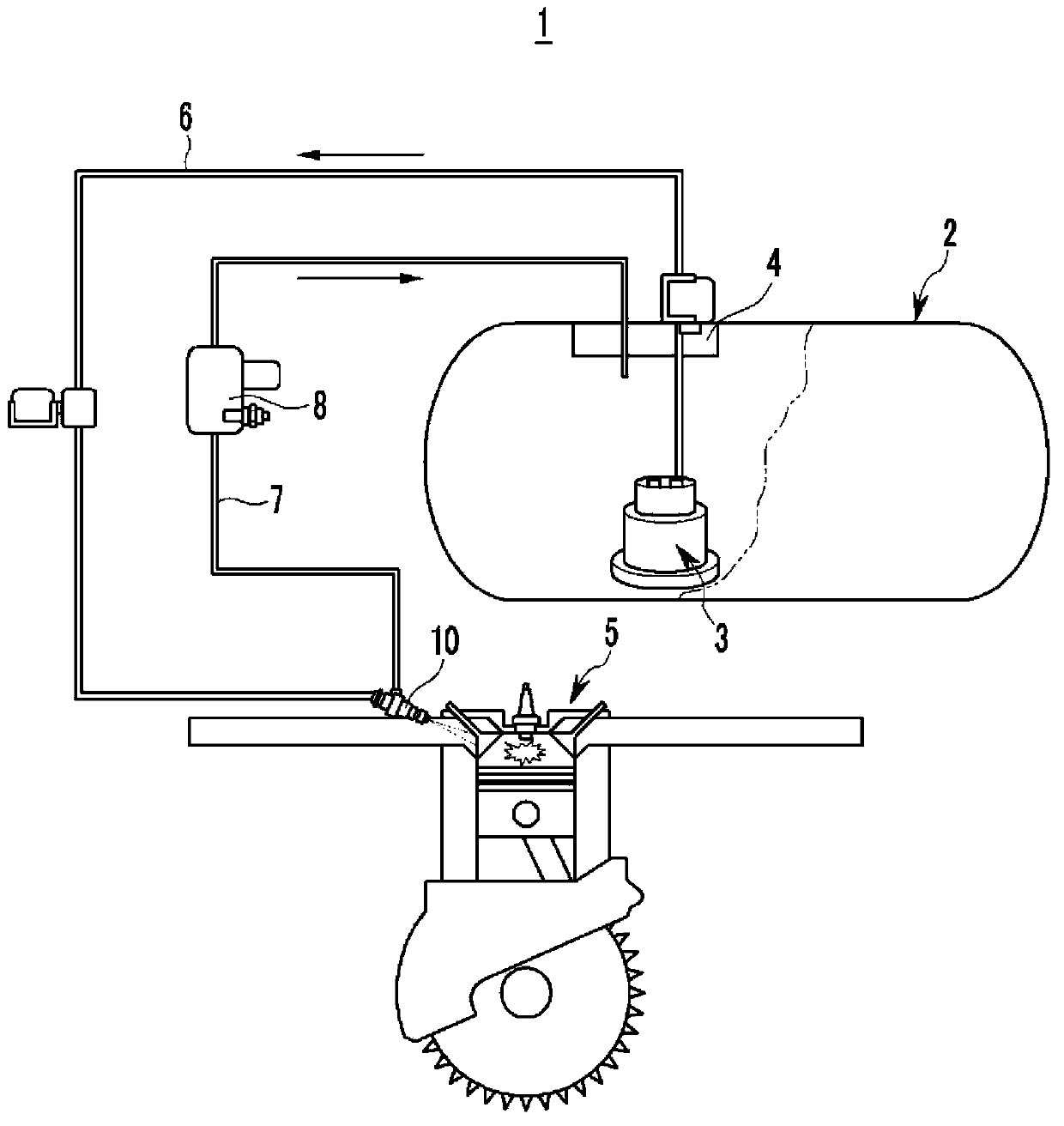
Since a large amount of return fuel is heated by the engine 5, the temperature inside the LPG tank 2 rises over time, so the pressure inside the tank increases at the same time, making poor filling when the LPG fuel is refilled
In addition, there is a problem in that noise is generated in the LPG fuel pump 3 due to excessive return velocity and pump operation, and the durability of the LPG fuel pump 3 is deteriorated
[0010] Meanwhile, in order to solve the problem, if the performance of the LPG fuel pump 3 is generally lowered, the amount of returned fuel decreases in the low load region, so the temperature inside the LPG gas tank 2 decreases, but deterioration of the performance of the engine in the high load region occurs The problem

Method used


Image

  • System and method for controlling LPG pump and fuel supplying system of LPI engine
  • System and method for controlling LPG pump and fuel supplying system of LPI engine
  • System and method for controlling LPG pump and fuel supplying system of LPI engine

Examples


Embodiment Construction

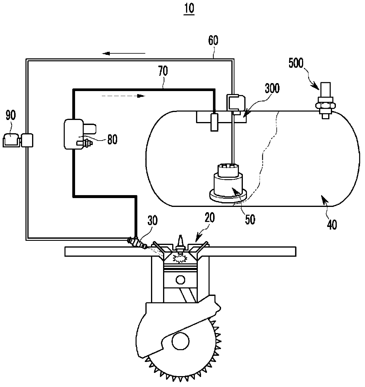
[0038]Reference will now be made in detail to various embodiments of the invention, examples of which are illustrated in the accompanying drawings and described below. While the invention has been described in conjunction with exemplary embodiments, it will be understood that present description is not intended to limit the invention to those exemplary embodiments. On the contrary, the invention is intended to cover not only the exemplary embodiments, but also various alternatives, modifications, equivalents and other embodiments, which may be included within the spirit and scope of the invention as defined by the appended claims.

[0039] Exemplary embodiments of the present invention will be described in detail below with reference to the accompanying drawings.

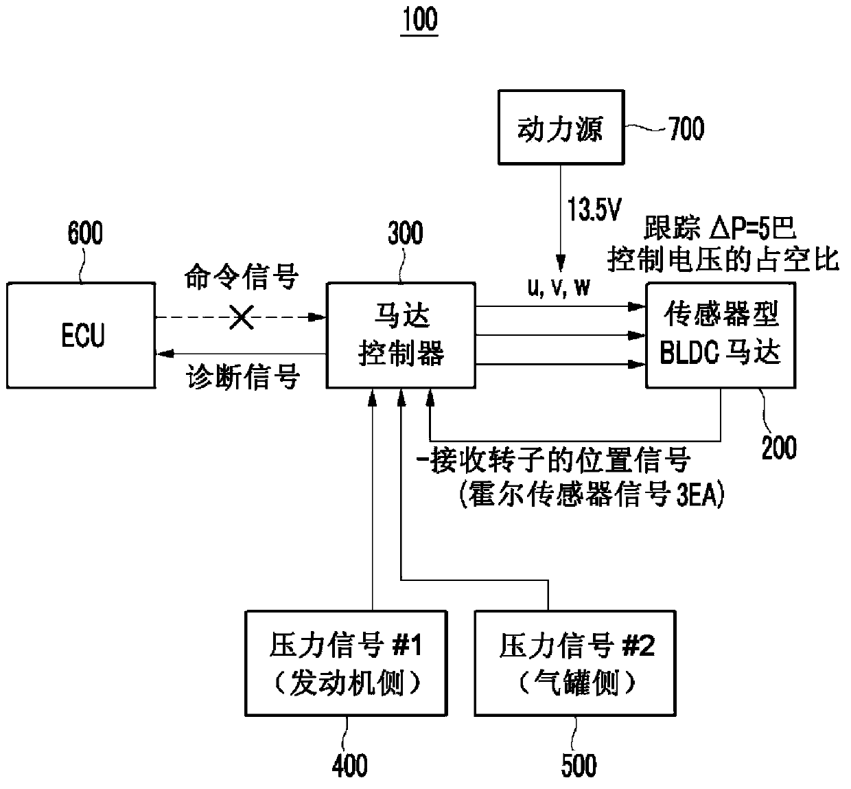
[0040] figure 2 is a block diagram of a fuel supply system 10 of an LPI engine according to an exemplary embodiment of the present invention, image 3 is a block diagram showing an LPG fuel pump control system 10...


PUM


Abstract

A method of controlling a liquefied petroleum gas (LPG) fuel pump may include driving a motor of the LPG fuel pump with a voltage of a predetermined duty, measuring a driving speed of the motor, changing the predetermined duty of the motor so that the measured driving speed of the motor reaches a target speed when the measured driving speed of the motor may be not equal to the target speed, measuring pressure of an LPG bombe and pressure of an injector, and changing the target speed when a first difference between the measured pressure of the LPG bombe and the measured pressure of the injector may be not maintained as a first predetermined value.

Description

[0001] Cross References to Related Applications [0002] This application claims priority from Korean Patent Application No. 10-2012-0098870 filed on Sep. 6, 2012, the entire contents of which are hereby incorporated by reference for all purposes. technical field [0003] The present invention relates to a system and method for controlling an LPG fuel pump for delivering liquefied petroleum gas (LPG) fuel, and a fuel supply system for a liquefied petroleum injection (LPI) engine using the LPG fuel pump control system. Background technique [0004] figure 1 It is a structural diagram of a liquefied petroleum injection (LPI) fuel storage and supply system in the related art. [0005] Such as figure 1 As shown in , the LPI fuel storage and supply system 1 in the related art generally includes an LPG gas tank 2 for storing LPG fuel, an LPG fuel pump 3 for delivering the stored LPG fuel, a pump controller 4 for controlling the LPG fuel pump 3, and providing LPG The fuel supply...

Claims


Application Information

Patent Timeline
Patent Type & Authority Applications(China)
IPC IPC(8): F02D19/02F02M21/02
CPCF02D41/0027F02D41/3082F02D2041/2027F02D2200/0602F02D2250/31F02M21/0212Y02T10/30F02M21/02F02M37/08F02M51/04
Inventor 咸昌昊崔弼善
Owner HYUNDAI MOTOR CO LTD
Learn More