Ultraviolet irradiation apparatus

An irradiation device and ultraviolet technology, which are applied to irradiation devices, lighting devices, lighting auxiliary devices, etc., can solve the problems of increasing the separation distance of the support body, increasing the distance of the support substrate 2, and the power source 41 and the transformer 42 reaching heat-resistant temperature damage. , to achieve the effect of suppressing the temperature rise and not increasing the temperature

Active Publication Date: 2009-04-08
USHIO DENKI KK
View PDF4 Cites 0 Cited by
  • Summary
  • Abstract
  • Description
  • Claims
  • Application Information

AI Technical Summary

Problems solved by technology

[0018] In addition, if the overall length of the ultraviolet lamp 1 increases, the substrate 2 for fixing the ultraviolet lamp 1 will also increase.
[0019] On the other hand, if the object to be processed is enlarged, the processing chamber will also be enlarged, and the separation distance of the support supporting the ultraviolet irradiation device will increase.
[0020] That is, since the two ends A of the substrate 2 are straddled on the supporting body 93, the distance between the two ends A of the supporting substrate 2 must be increased.
[0021] And, since the power supply 41 and the transformer 42 are directly arranged on the substrate 2, if the distance between the two ends A of the supporting substrate 2 increases, the amount of deformation of the substrate 2 will increase, and the separation distance between the ultraviolet lamp 1 and the object W will change. Specifically, in the direction of the tube axis of the ultraviolet lamp, there are positions where the separation distance between the lamp and the object to be heated is large and the position is small, and there is a problem that the object to be heated cannot be treated uniformly.
[0022] In addition, there is a tendency to increase the output of the ultraviolet lamp 1 in order to increase the processing speed of the processed object, and the substrate 2 is further heated by the heat radiated from the ultraviolet lamp 1. Since the power supply 41 and the transformer 42 are directly arranged on the substrate 2, there is a power supply. The problem that 41 and transformer 42 are destroyed when they reach the heat-resistant temperature or higher

Method used


Image

  • Ultraviolet irradiation apparatus
  • Ultraviolet irradiation apparatus
  • Ultraviolet irradiation apparatus

Examples


Embodiment Construction

[0047] Hereinafter, the ultraviolet irradiation device of this invention is demonstrated using drawing.

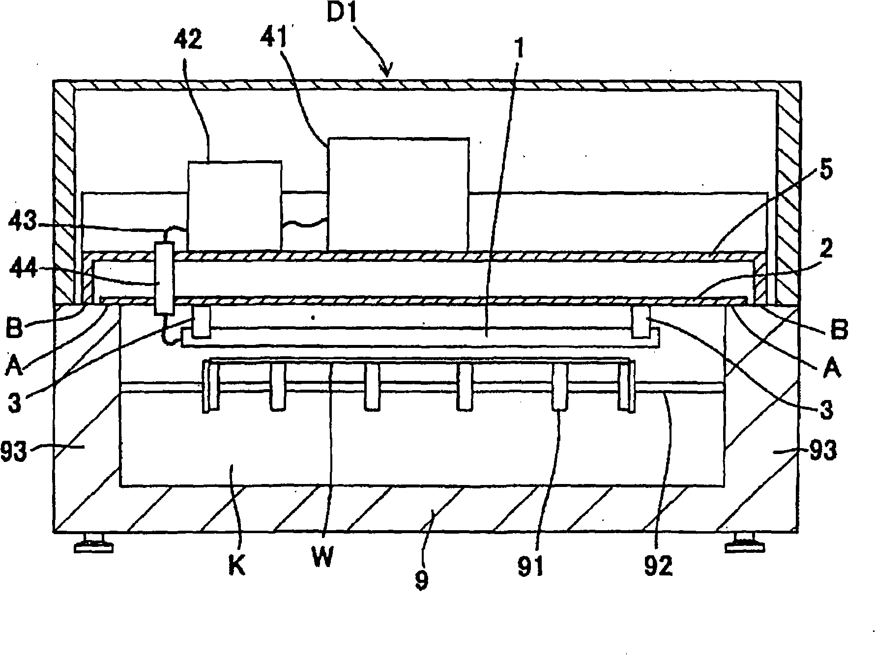
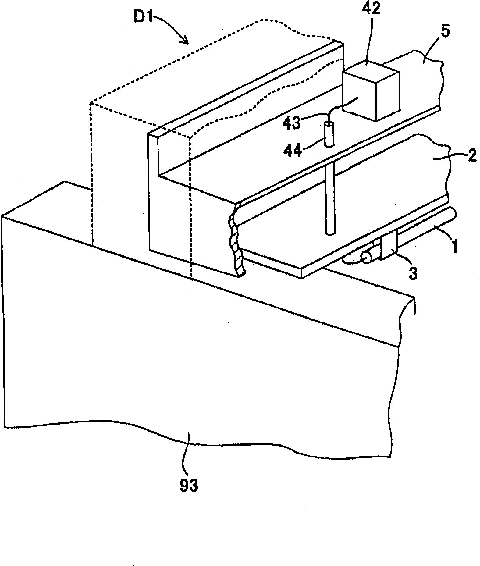
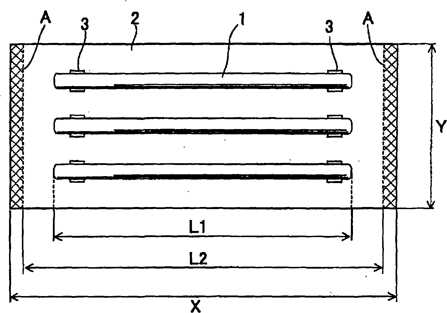
[0048] figure 1 It is a structural explanatory diagram in which the ultraviolet irradiation device of the present invention is arranged on the processing chamber, figure 2 is viewed from above the processing chamber figure 1 Partial cut-away perspective view of the ultraviolet irradiation device of , image 3 It is viewed from the direction of the ultraviolet light figure 1 A top view of the UV irradiation setup.

[0049] Such as figure 1As shown, the processing chamber 9 is the same structure as the processing chamber described in the prior art, and has a processing space K with an upper opening. In the processing chamber 9, a conveying roller 91 is installed on a roller shaft 92, and the conveying roller 91 is rotated to convey The processed object W is irradiated with ultraviolet rays to treat the processed object.

[0050] In addition, in the treatment chamb...


PUM


Abstract

Provided is an ultraviolet irradiation device, which can maintain a constant separation distance between the ultra-violet ray lamp and the object to be processed and can equably process the object to be heated, wherein, the substrate for fixing the ultra-violet ray lamp will not deform. The inventive ultraviolet irradiation device has a tube-shaped ultraviolet lamp (1), and an ultraviolet irradiation device (D1) is configured at the upper part of a process room (9) with an opening at the upper side. The ultraviolet irradiation device (D1) is characterized by including a substrate (2) for supporting the ultra-violet lamp (1), lighting-up units (41,42) for lighting up the ultra-violet lamp (1), and a construction plate (5) provided with the lighting-up units (41,42). Both ends of the tubular axis direction of the ultra-violet ray lamp (1) of the substrate (2) are provided on a support body (93), the support body (93) supports the ultraviolet irradiation device provided in the process room (9), the central part of the construction plate (5) is separated from the substrate (2), and the self weight of the construction plate (5) is exerted onto support body (93).

Description

technical field [0001] The present invention relates to an ultraviolet irradiation device for irradiating vacuum ultraviolet rays radiated from an ultraviolet lamp such as an excimer lamp to a processed object for cleaning or modification. Background technique [0002] The ultraviolet lamp that utilizes in ultraviolet irradiation device, known has Figure 11 The excimer lamp shown. [0003] The excimer lamp 1 is a hollow cylindrical tube lamp in which an inner tube 11 and an outer tube 12 are arranged coaxially. The inner tube 11 and the outer tube 12 are made of quartz glass as a dielectric. A grid-shaped external electrode 13 is formed on the outer surface of the outer tube 12, and the ultraviolet rays generated in the discharge space S are irradiated from the gaps in the grid. On the outer surface of the inner tube 11, the external electrode is formed of a metal plate having a C-shaped cross section. 14. [0004] The discharge space S is filled with a rare gas such as x...

Claims


Application Information

Patent Timeline
Patent Type & Authority Applications(China)
IPC IPC(8): G21K5/00F21V19/00F21V21/00B08B7/00
CPCB08B7/00H01J5/50H01J61/72H01J65/00H01J65/046
Inventor 菅敏幸远藤真一
Owner USHIO DENKI KK
Why Eureka
Try Eureka