Check patentability & draft patents in minutes with Patsnap Eureka AI!

Spark-ignition direct injection engine

A spark ignition, engine technology, used in engine components, engine control, combustion engines, etc., can solve problems such as pressure rise and combustion noise increase

Active Publication Date: 2014-03-26
MAZDA MOTOR CORP
View PDF8 Cites 2 Cited by
  • Summary
  • Abstract
  • Description
  • Claims
  • Application Information

AI Technical Summary

Problems solved by technology

In an engine that performs such compression ignition combustion, as the engine load increases, the compression ignition combustion becomes a combustion in which the pressure rises sharply, resulting in an increase in combustion noise.

Method used


Image

  • Spark-ignition direct injection engine
  • Spark-ignition direct injection engine
  • Spark-ignition direct injection engine

Examples


Embodiment Construction

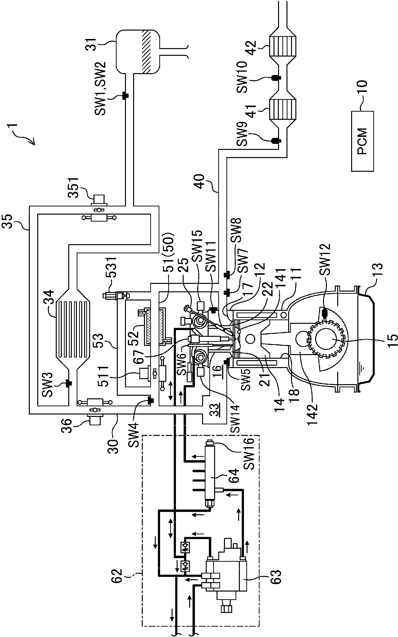
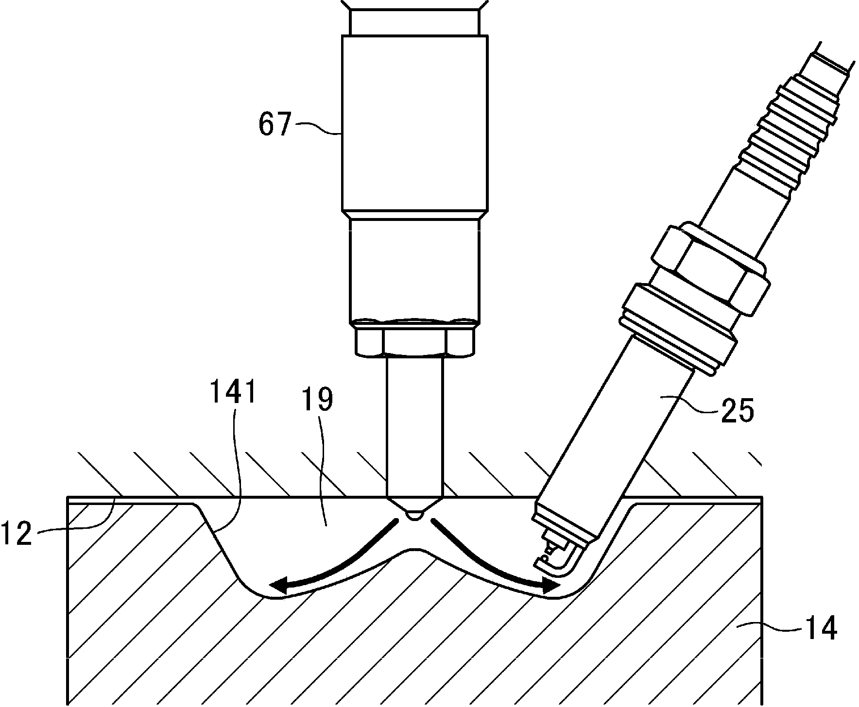
[0074] Hereinafter, an embodiment of a spark ignition type direct injection engine will be described based on the drawings. The description of the following preferred embodiments is merely an illustration. figure 1 , figure 2 The schematic structure of the engine (engine main body) 1 is shown. The engine 1 is a spark-ignition gasoline engine that is mounted on a vehicle and supplied with fuel containing at least gasoline. The engine 1 has a cylinder block 11 provided with a plurality of cylinders 18 (in addition, in figure 1 Although only one cylinder is shown in the figure, for example, four cylinders can be arranged in series), the cylinder head 12 arranged on the cylinder block 11, and the oil sump arranged on the lower side of the cylinder block 11 and retaining lubricating oil shell13. A reciprocating piston 14 is embedded in each cylinder 18 , and the piston 14 is connected to the crankshaft 15 through a connecting rod 142 . On the top surface of the piston 14, suc...


PUM


Abstract

A spark-ignition direct injection engine is provided. A controller (10) sets the fuel pressure to 30 MPa or above when an engine main body (1) runs within a specific part, including a boundary of a first range and a second range and high in load, of the first range, and drives a fuel injection valve (67) to inject fuel into a cylinder in a period at least from a late stage of compression stroke to an early stage of expansion stroke, such that the compression ignition is started after a compression top dead center. Moreover, When the engine main body (1) runs within a range, lower than the specific part in load, in the first range, the controller drives the fuel injection valve (67) to inject the fuel into the cylinder in a period at least from intake stroke to a mid-stage of the compression stroke.

Description

technical field [0001] The technology disclosed herein relates to spark ignition direct injection engines. Background technique [0002] For example, as described in Patent Document 1, as a technique for achieving both improvement of exhaust emission performance and improvement of thermal efficiency, a combustion form in which air-fuel mixture in a cylinder is compressed and ignited is known. In an engine that performs such compression ignition combustion, as the engine load increases, the compression ignition combustion becomes combustion in which the pressure rises sharply, leading to an increase in combustion noise. Therefore, as described in Patent Document 1, even an engine that performs compression ignition combustion generally does not perform compression ignition combustion but performs spark ignition combustion by driving the spark plug in a high-load operating range. [0003] Patent Document 2 describes a technique in which, like the engine of Patent Document 1, i...

Claims


Application Information

Patent Timeline
IPC IPC(8): F02P5/145F02D45/00
CPCF02D41/0057F02D41/3017F02B23/101F02B29/0418F02D9/04F02D13/0207F02D13/0219F02D13/0273F02M26/25F02M26/01F02M26/47Y02T10/12Y02T10/40F02D41/30
Inventor 岩井浩平山川正尚长津和弘养祖隆
Owner MAZDA MOTOR CORP
Features
  • R&D
  • Intellectual Property
  • Life Sciences
  • Materials
  • Tech Scout
  • Unparalleled Data Quality
  • Higher Quality Content
  • 60% Fewer Hallucinations
Learn More