
Fluid machinery with a rotary piston structure

A technology of fluid machinery and piston, which is applied in the field of machinery manufacturing to achieve the effect of increasing the filtration pressure difference, high pressure, stable operation and no noise

Inactive Publication Date: 2016-06-08
王五一
View PDF6 Cites 0 Cited by
  • Summary
  • Abstract
  • Description
  • Claims
  • Application Information

AI Technical Summary

Problems solved by technology

However, the piston’s circumcircle translation and crossing structure has not been involved so far, but to realize it, the problem of the piston’s circumcircle translation must be solved
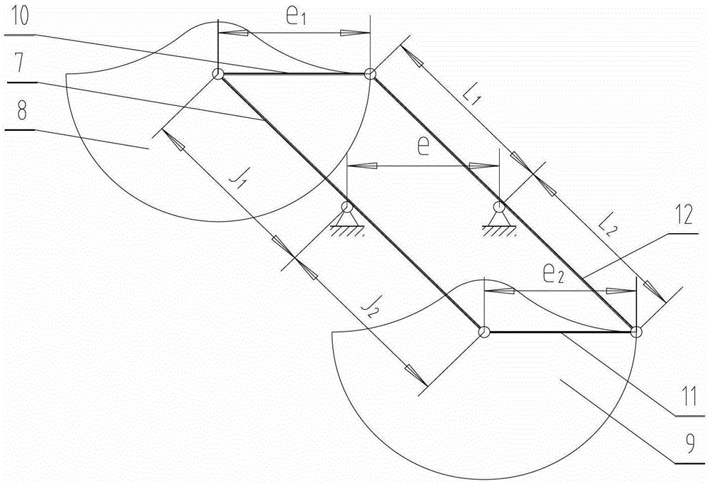
According to the motion characteristics of the connecting rod in the constant velocity double crank transmission mechanism, the present invention successfully solves this problem and creates an ideal product structure such as pumps (motors)

Method used


Image

  • Fluid machinery with a rotary piston structure
  • Fluid machinery with a rotary piston structure
  • Fluid machinery with a rotary piston structure

Examples


Embodiment Construction

[0017] The working principle and specific implementation of the hydraulic pump of the fluid machine with the rotary piston structure of the present invention will be further described below in conjunction with the accompanying drawings:

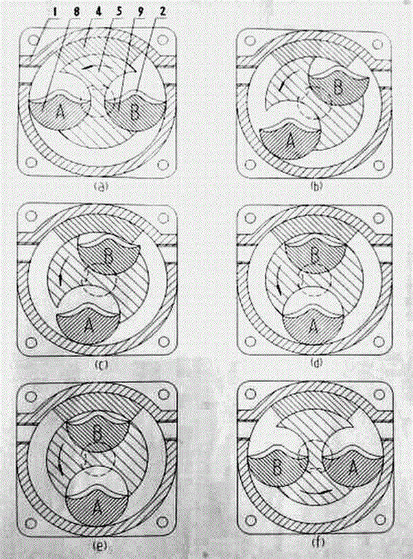
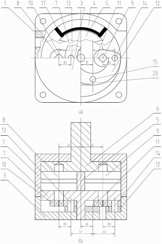
[0018] Such as figure 1 a. figure 2 It can be seen that the hydraulic pump of the embodiment of the present invention is mainly composed of a housing 1, a housing end cover 3, a start and end partition body 4, a rotor core block 5, rotor side covers 6, 7, pistons 8, 9, connecting rods 10, 11 and multi-connection Crank ring 12 etc. are formed. The rotor core block 5 is located in the casing 1, the rotor side covers 6, 7 are located at both ends of the rotor core block 5, and the casing 1 and the rotor form a closed annular cylinder. The start-end partition body 4 is located on the housing 1, forming a circular "C"-shaped annular cylinder. The pistons 8, 9 are located in two symmetrically distributed circular grooves of the rotor core block...


PUM


Abstract

The invention relates to pumps with revolving piston structures, related products and a part of embodiments. Each pump is characterized in that the pump comprises a C-shaped annular cylinder body which is composed of multiple parts, the piston of the pump is pulled and controlled through a double crank transmission mechanism and carries out circular revolving translation around the cylinder body under the driving of a rotor. The pump has the characteristics of simple structure, easy manufacturing, low wear, high rotating limit speed and direct ratio liner change of the volume. When the pumps are used for manufacturing metering pumps and flow meters, micro-metering and precision metering can be achieved; when the pumps are used for manufacturing hydraulic pumps (motors), the hydraulic pumps are smooth in flow rate, free of noise, good in hydroscopicity and low in cost and can be used to replace gear pumps (motors), centrifugal self-priming pumps, submersible pumps and the like; when the pumps are used in fluid pumps such as fire pumps, water supply pumps for buildings and the like, the fluid pumps are high in pressure and energy-saving; when the pumps are used in hydraulic water lifting pumps and dust-removing negative-pressure suction fans, the energy consumption can be greatly reduced, the energy utilization rates of power devices for hydroelectric generation can be improved. The pumps are also high in vacuum degree and can be used for manufacturing vacuum pumps. The structures of the pumps are ideal pump structures and extremely wide in application scope and market prospect.

Description

technical field [0001] The invention belongs to the field of mechanical manufacturing, and relates to a variety of mechanical devices with the same structure. More specifically, it is a kind of simple and economical manufacturing, accurate flow linearity, low wear and long life, small volume and high efficiency. It is applied to positive displacement pumps. A kind of mechanical structure and all related products derived from such products are used to realize the transfer, measurement and mechanical transmission of various gases, liquids, etc. Mainly include hydraulic pumps, hydraulic motors, metering pumps, flow meters, oil pumps, water pumps (especially fire pumps and high-rise water supply pumps with high pressure requirements), chemical pumps, food pumps, air pumps, vacuum pumps, negative pressure fans for dust collectors, and even hydraulic pumps power generation device, etc. Background technique [0002] Since the present invention is an invention of a mechanical struc...

Claims


Application Information

Patent Timeline
Patent Type & Authority Patents(China)
IPC IPC(8): F04C2/08F03C2/08F03B13/00
Inventor 王五一
Owner 王五一
Learn More