Combined type heat exchange unit

A heat exchange unit and compound technology, which is applied in the field of heat exchange units and compound heat exchange units, can solve the problems of inability to effectively recover waste heat resources from waste heat sources, difficulties in reducing the outlet water temperature below 35°C, insufficient driving force of absorption heat pumps, etc. problems, to achieve the effect of reducing the power consumption of water pumps, reducing initial investment, and alleviating insufficient heating capacity

Inactive Publication Date: 2014-03-26
TSINGHUA UNIV
View PDF6 Cites 32 Cited by
  • Summary
  • Abstract
  • Description
  • Claims
  • Application Information

AI Technical Summary

Problems solved by technology

[0003] 1) Restricted by the water supply temperature of the heating network: Due to the design temperature or operating years of some heating systems, the primary network cannot deliver hot water exceeding 115°C, resulting in low water temperature entering the generator of the absorption heat pump heat exchange unit. For the absorption heat pump, the driving force will be insufficient, so it is difficult for the outlet water temperature of the absorption heat pump heat exchange unit to drop below 35°C, which limits the exp

Method used


Image

  • Combined type heat exchange unit
  • Combined type heat exchange unit
  • Combined type heat exchange unit

Examples


Embodiment 1

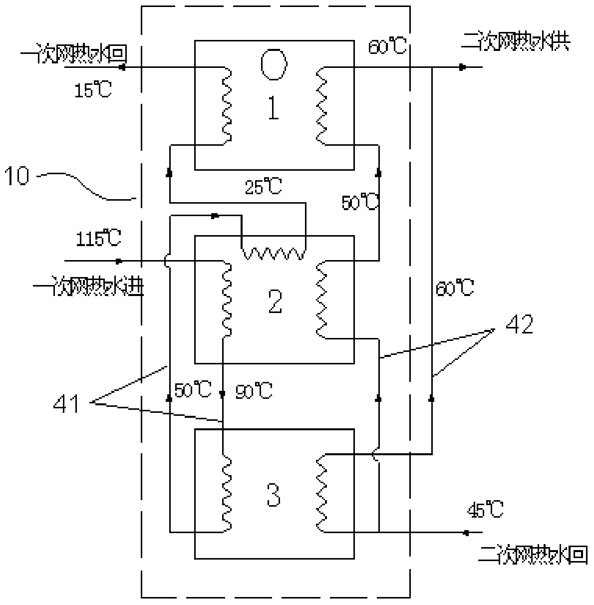
[0029] Embodiment 1: as figure 1As shown, in actual operation, the 115°C primary network hot water inflow output by the centralized heat source enters the generator of the absorption heat pump 2 as the driving heat source to heat the concentrated lithium bromide solution in the absorption heat pump 2; the heat is released and the temperature is lowered to 90°C After left and right, it flows out from the generator of the absorption heat pump 2, and enters the water-water heat exchanger 3 as a heating source to heat the hot water in the secondary network; after the heat release cools down to about 50°C, it flows out of the water-water heat exchanger 3, and then enters The evaporator of the absorption heat pump 2 is used as a low-grade heat source; the evaporator of the compression heat pump 1 is used as a low-grade heat source after the heat release is cooled to about 25°C, and the heat is sent back to the centralized heat source after the heat release is cooled to about 15°C, an...

Embodiment 4

[0031] Embodiment 4: as Figure 4 As shown, in actual operation, the 115°C primary network hot water inflow output by the centralized heat source enters the generator of the absorption heat pump 2 as the driving heat source to heat the concentrated lithium bromide solution in the absorption heat pump 2; the heat is released and the temperature is lowered to 90°C After left and right, it flows out from the generator of the absorption heat pump 2, and enters the secondary water-water heat exchanger 3b as a heating source to heat the hot water in the secondary network; after the heat is released and cooled to about 65°C, it flows from the secondary water-water heat exchanger 3b flow out, and then enter the first-level water-water heat exchanger 3a to heat the hot water in the secondary network; after cooling down to 50°C, it flows out from the first-level water-water heat exchanger 3a, and then enters the evaporator of the absorption heat pump 2 as a low High-grade heat source: A...


PUM


Abstract

The invention relates to a combined type heat exchange unit. The combined type heat exchange unit is characterized in that a compression heat pump, an absorption heat pump, more than one water-water heat exchanger and connecting pipelines are included; the connecting pipelines are divided into the primary side pipeline and the secondary side pipeline; the primary side pipeline is in a step-by-step series connection, namely the primary side pipeline is sequentially communicated with a generator of the absorption heat pump, the water-water heat exchanger, an evaporator of the absorption heat pump and an evaporator of the compression heat pump; the secondary side pipeline is communicated to a heat consumer in the mode of first parallel connection and then series connection or step-by-step series connection or independent separating connection. According to the combined type heat exchange unit, the heat of primary network hot water can be utilized in a gradient mode, so that the temperature difference of water supply and water return of primary network hot water of a centralized heating system is greatly increased. Accordingly, the initial investment of a pipeline system and the power consumption of water pump operation can be greatly reduced, conditions are created for utilizing low-grade heat energy and even waste heat and the like of a power source, the comprehensive energy utilization efficiency of the system is improved, and the heat supply cost is lowered.

Description

technical field [0001] The invention relates to a heat exchange unit used for heating and hot water supply, in particular to a composite heat exchange unit capable of greatly increasing the temperature difference between primary network hot water supply and return water in a central heating system, belonging to the field of energy technology . Background technique [0002] As the scale of urban central heating continues to increase, the high-temperature hot water generated by centralized heat sources often has to be transported over a long distance to reach the heat user. In order to expand the heating area, reduce transportation costs, and create conditions for the recovery of waste heat from power plants, Fu Lin of Tsinghua University and others proposed an invention patent with the patent number: ZL200810101064.5 and the invention name: "A heat pump heat exchange unit". This patent uses heat exchange and hot water driven absorption heat pump composite technology to solve...

Claims


Application Information

Patent Timeline
IPC IPC(8): F24D3/18
CPCY02B30/12
Inventor 付林张世钢唐道轲
Owner TSINGHUA UNIV
Why Eureka
Try Eureka