Coal combustion apparatus capable of separating carbon dioxide and separation method thereof

A carbon dioxide and coal combustion technology, applied in chemical instruments and methods, heating devices, using non-combustion exothermic chemical reactions to generate heat, etc. time, improve the processing capacity, strengthen the coal gasification reaction and the effect of

Inactive Publication Date: 2010-04-28
SOUTHEAST UNIV
View PDF1 Cites 26 Cited by
  • Summary
  • Abstract
  • Description
  • Claims
  • Application Information

AI Technical Summary

Problems solved by technology

The main problem is that the cost of emission reduction is too high, such as the regeneration of the absorbent captured by post-combustion, and the oxygen production process of pure oxygen combustion requires a large amount of energy consumption
Relevant data show that after-combustion capture and pure oxygen combustion will consume 25-28% of the power generated by the power station, and the cost of power generation will increase by 30-40%; the integrated coal gasification combined cycle technology of pre-combustion capture will also increase the cost of power generation by about 25%
The main reasons for the above-mentioned high cost of emission reduction are as follows: Most of the above-mentioned technologies use conventional coal combustion technology, that is, use air as the oxidant, and the one-step oxidation reaction process route, a large amount of nitrogen in the air enters the flue gas, thus generating nitrogen in the flue gas The concentration of carbon dioxide is very low, accounting for only 10-15%, which leads to the high cost of subsequent treatment of carbon dioxide, including concentration purification and compression landfill
[0004] Existing methods for separating carbon dioxide by chemical looping combustion and displaceable combustion methods, such as Chinese patents 03152977.1, 200510040519.3 and 200710118134.3, in the above three patents, the devices and methods used have the following disadvantages: First, the above patents use a slender circulating flow The fluidized bed is used as the air reactor, and the bubbling fluidized bed or spouted fluidized bed with a lower height is used as the fuel reactor; It is unreasonable in operation, because coal must undergo coal gasification reaction to become gaseous fuel, and then undergo reduction reaction with oxygen carrier, and the coal gasification reaction rate in the fuel reactor is faster than that of oxygen carrier in the air reactor The oxidation reaction is several orders of magnitude lower, so the existing fuel reactor structure cannot meet the time requirements of the entire system reaction; secondly, the above devices are all operated under normal pressure, and the separated carbon dioxide needs to be compressed later, which consumes a lot of energy; finally 1. The oxygen carrier is to use noble metal oxides such as nickel oxide, copper oxide or cobalt oxide, or to use cheap calcium sulfate. Although noble metal oxides have better reactivity, they are expensive. Supplementary oxygen carrier will cause a sharp increase in operating costs; cheap calcium sulfate oxygen carrier has the problem of sulfur dioxide precipitation during the reaction process, causing environmental problems

Method used


Image

  • Coal combustion apparatus capable of separating carbon dioxide and separation method thereof
  • Coal combustion apparatus capable of separating carbon dioxide and separation method thereof
  • Coal combustion apparatus capable of separating carbon dioxide and separation method thereof

Examples


Embodiment 1

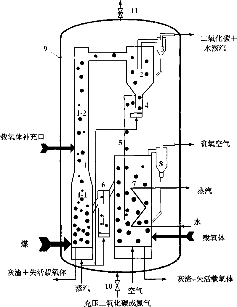
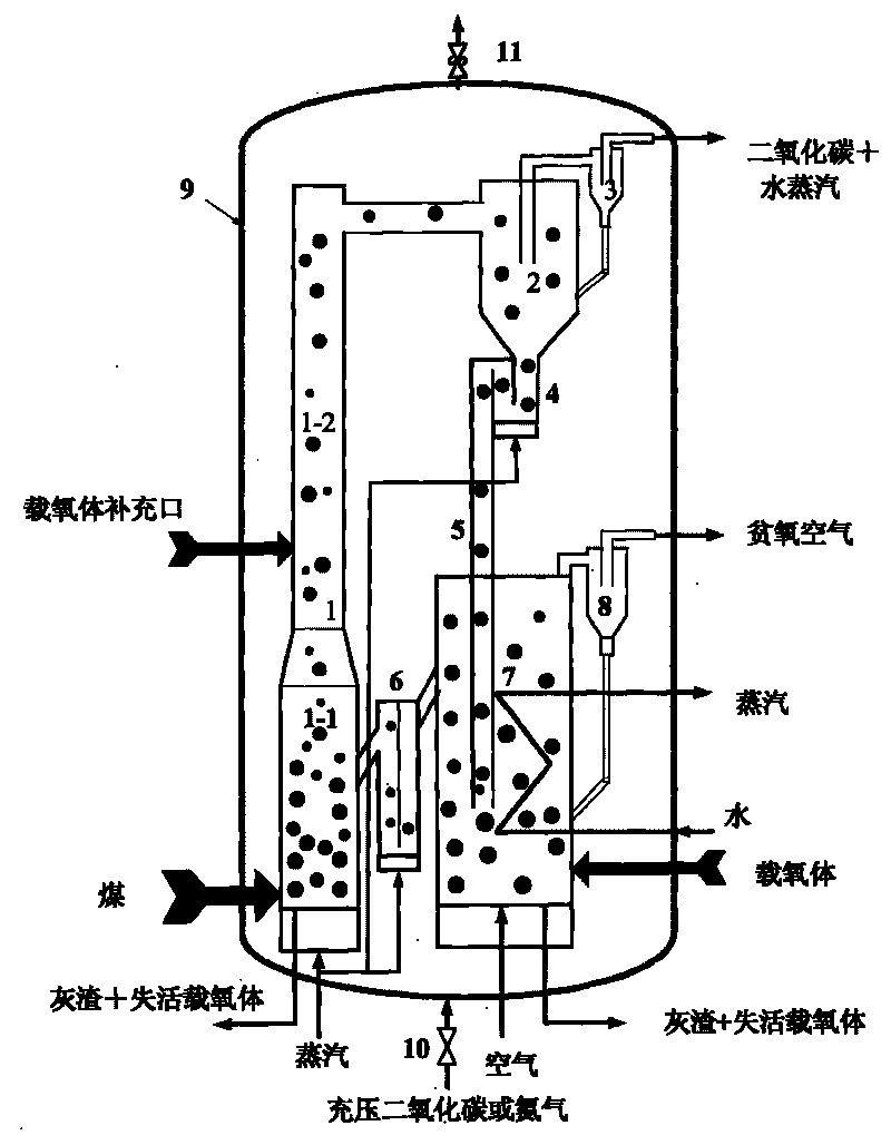
[0031] Such as figure 1 As shown, a coal combustion device capable of separating carbon dioxide is mainly composed of a fuel reactor 1, a primary cyclone separator 2, a dipleg 5 and an air reactor 7 connected in series, and it uses two independent reactors: the fuel reactor 1 and the air reactor 7, the lower part of the fuel reactor is a mixing chamber 1-1 with a large cross-section, and the upper part is a riser 1-2 with a small cross-section, and the height of the riser is more than three times that of the mixing chamber;

[0032] The whole system is arranged in a pressure shell 9 , and the pressure shell 9 is provided with a pressure charging valve 10 and a pressure relief valve 11 for adjusting the pressure in the pressure shell 9 .

[0033] The side outlet of the fuel reactor 1 is connected to the side inlet of the primary cyclone separator 2, and the upper part of the primary cyclone separator 2 is a flue gas outlet connected to the side of the secondary cyclone separato...

Embodiment 2

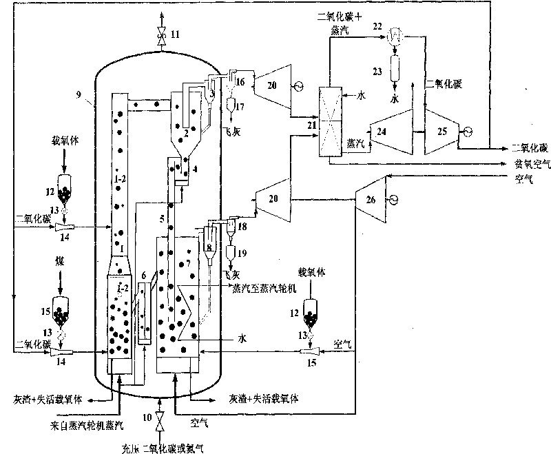
[0045] Such as figure 2 As shown, the power generation system using a coal combustion device that can separate carbon dioxide, the system consists of a coal combustion device that can separate carbon dioxide, an ash dust removal system, a coal and oxygen carrier feeding system, a flue gas turbine 20, a steam turbine 24, and an air compressor 26. Carbon dioxide compressor 25, waste heat boiler 21 and other components. The specific working method is as follows:

[0046] Coal is put into the coal tank 15, the feed valve 13 controls the amount of coal fed, and the recirculated carbon dioxide is sent to the mixing chamber 1-1 in the lower part of the fuel reactor by the conveying injector as conveying gas, and the coal particles are small particles in the range of 0-2mm , to facilitate pneumatic transportation and coal gasification reaction.

[0047] After the coal particles enter the mixing chamber 1-1, they are quickly mixed with the high-temperature bed material (mainly oxyge...


PUM


Abstract

The invention provides a coal combustion apparatus capable of separating carbon dioxide, which is mainly formed by connecting a fuel reactor, a primary cyclone separator, a dipleg and an air reactor in series; wherein the lower part of the fuel reactor is provided with a mixing chamber with large cross section, and the upper part thereof is provided with a lifting tube with small cross section; and the height of the lifting tube is over three times higher than that of the mixing chamber. The invention also provides a method using the coal combustion apparatus capable of separating the carbon dioxide to separate the carbon dioxide. The fuel reactor adopts the structure of a reactor with long residence time, internal circulation can be formed by granules, and the gas-solid turbulence is improved; the air reactor adopts a moving fluidized bed to ensure the operation to be stable, so that the heat can be evenly released; meanwhile, a heat exchanger is arranged inside the bed, so that coking caused by local overheating since a great deal of heat is released in a centralized way in oxidation reaction can be avoided. Furthermore, the fuel reactor and the air reactor run under the pressure, so that the equipment can be compact, the utilization efficiency of system energy is high, and the subsequent carbon dioxide compression energy consumption is reduced.

Description

technical field [0001] The invention belongs to the field of coal-fired carbon dioxide separation and emission reduction, and in particular relates to a coal combustion device capable of separating carbon dioxide; the invention also relates to a method for separating carbon dioxide by using the coal combustion device. Background technique [0002] The carbon dioxide emitted by burning fossil fuels (coal, oil and natural gas) is the main cause of global warming. However, with the deepening of people's understanding, the serious impact of global warming on human survival and social development has attracted worldwide attention. Widely concerned by various countries, the reduction and control of carbon dioxide emissions has become the consensus of the whole society. my country's coal-based energy structure determines that reducing carbon dioxide emissions will become one of the main contents of sustainable development in the future. [0003] At present, there are mainly three ...

Claims


Application Information

Patent Timeline
Patent Type & Authority Applications(China)
IPC IPC(8): F24J1/00C01B31/20F24V30/00C01B32/50
Inventor 肖睿张帅金保升钟文琪宋启磊
Owner SOUTHEAST UNIV
Why Eureka
Try Eureka