A kind of mechanical compression device and optical fiber connector

A technology of optical fiber connector and pressing device, which is applied in the field of optical communication, can solve the problems of optical fiber glue fragmentation, etc., achieve the effect of providing smoothness, improving the yield rate, and reducing the insertion loss rate

Active Publication Date: 2015-12-02
SHENZHEN ZHAOWEI MACHINERY&ELECTRONICS CO LTD
View PDF3 Cites 0 Cited by
  • Summary
  • Abstract
  • Description
  • Claims
  • Application Information

AI Technical Summary

Problems solved by technology

For this reason, there is no need to have strict requirements on the thickness of the product, but if there is a displacement between the pressing block and the optical fiber during the pressing process, it may be that the optical fiber is broken and the rubber is broken.

Method used


Image

  • A kind of mechanical compression device and optical fiber connector
  • A kind of mechanical compression device and optical fiber connector
  • A kind of mechanical compression device and optical fiber connector

Examples


Embodiment 1

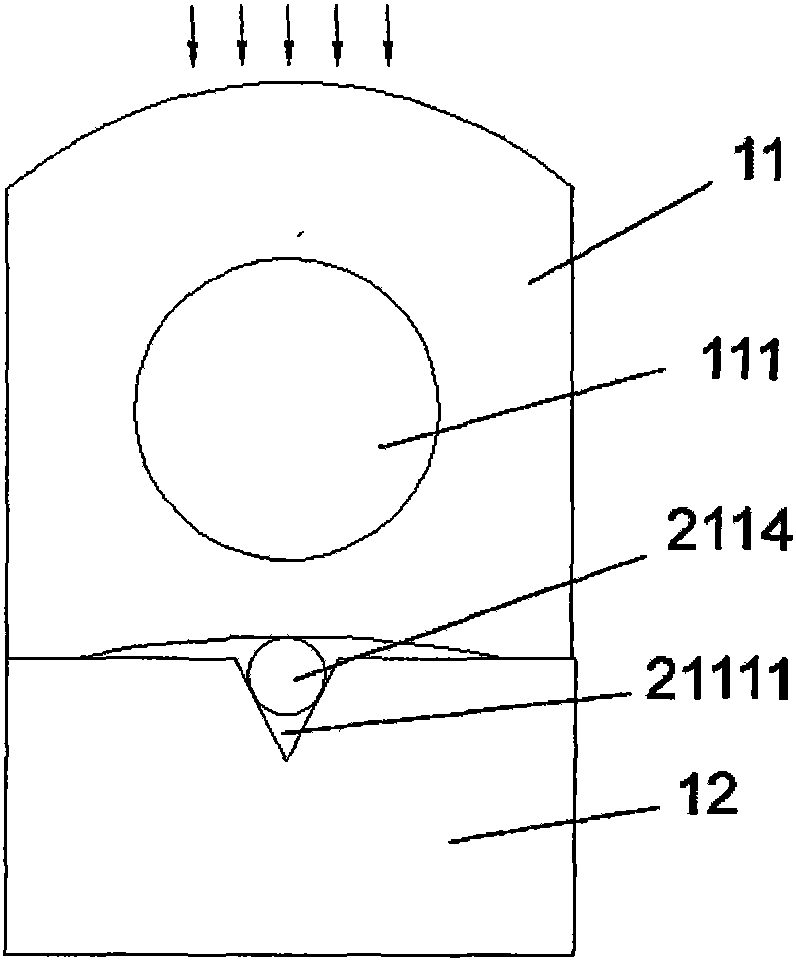
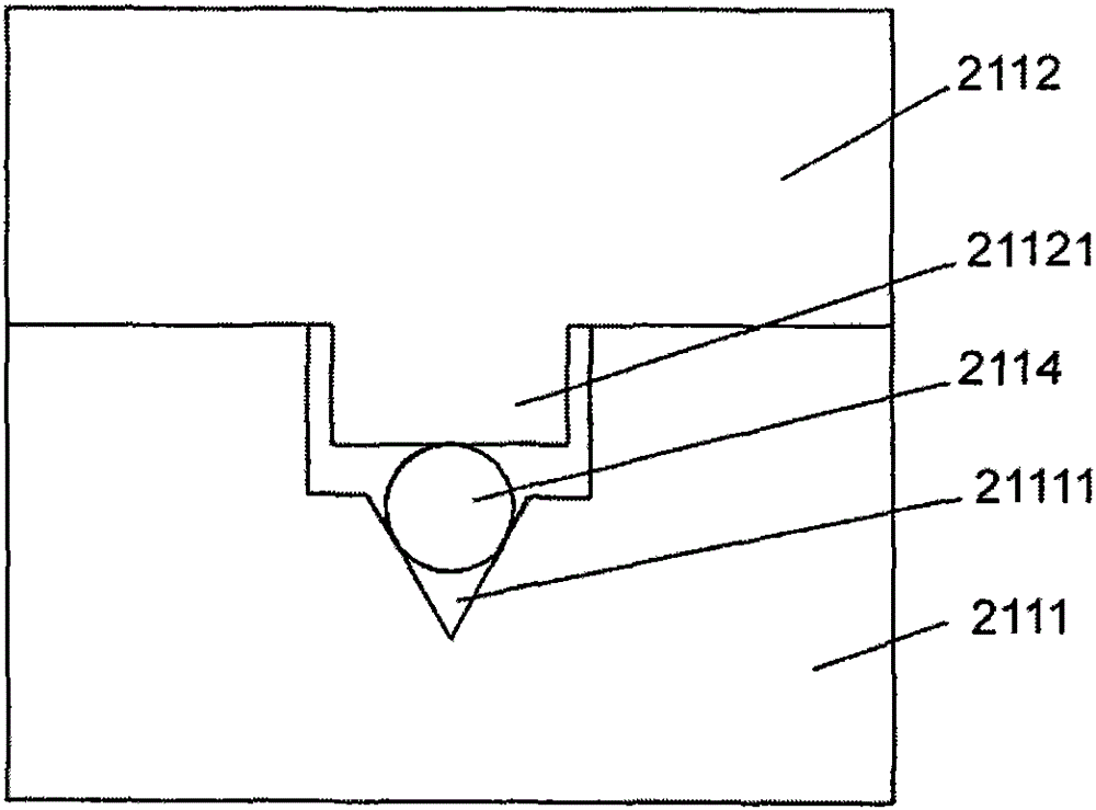
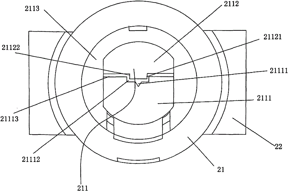
[0035] The invention provides a mechanical pressing device of an optical fiber connector and an optical fiber connector with the mechanical pressing device. like Figure 2-3 As shown, the optical fiber connector 20 includes a main body 21 of a hollow structure and a jacket 22 arranged on the periphery of the main body. The main body 21 is provided with a mechanical pressing device 211, and the mechanical pressing device 211 includes a V-groove base plate 2111, The V-groove base plate 2111 has a V-shaped groove 21111 for embedding optical fiber ferrules, a V-groove pressing block 2112, a fixing sleeve (not shown in the figure) and a sliding pressure sleeve 2113, and the V-groove base plate 2111 and the V-groove The pressing block 2112 is placed inside the cavity of the fixing sleeve, the sliding pressing sleeve 2113 is sleeved on the outside of the fixing sleeve, one side of the V-groove substrate 2111 is provided with a groove 21112, and the V-groove pressing block 2112 A bos...

Embodiment 2

[0037] This embodiment provides another mechanical pressing device for an optical fiber connector and an optical fiber connector with the mechanical pressing device. like Figure 4-9As shown, the optical fiber connector 20 includes a main body 21 of a hollow structure and a jacket 22 arranged on the periphery of the main body. The main body 21 is provided with a mechanical pressing device 211, and the mechanical pressing device 211 includes a V-groove base plate 2111, The V-groove substrate 2111 has a V-shaped groove 21111 for embedding optical fiber ferrules, a V-groove pressing block 2112, a fixed sleeve 2115 and a sliding pressing sleeve 2113, and the V-groove base plate 2111 and the V-groove pressing block 2112 are fixed Inside the cavity of the sleeve, the sliding press sleeve 2113 is sleeved on the outside of the fixed sleeve, one side of the V-groove base plate 2111 is provided with a boss 21121, and one side of the V-groove pressing block 2112 is provided with a groove...


PUM


Abstract

The invention discloses a mechanical pressing device of an optical-fiber connector and an optical-fiber connector which is provided with the mechanical pressing device. The mechanical pressing device of the optical-fiber connector includes a V-groove substrate. The V-groove substrate is provided with a V-shaped groove used for burying an optical-fiber insert core, a V-groove press block, a fixed sleeve and a sliding pressing sleeve. The V-groove substrate and the V-groove press block are arranged in a cavity of the fixed sleeve. The sliding pressing sleeve is sleeved outside the fixed sleeve. The mechanical pressing device is characterized in that the V-groove substrate cooperates with the V-groove press block through a groove; a boss is in cooperation with the groove; the V-shaped groove is arranged on the boss or in the groove; and when the V-groove substrate and the V-groove press block contact, the boss or the groove contacts the optical-fiber insert core. Even if the V-groove substrate and the V-groove press block are subjected to extrusion, faces which bear the force first are step faces of the V-groove substrate and the V-groove press block so that a problem that the optical-fiber insert core in the V-shaped groove is overly pressed is prevented.

Description

【Technical field】 [0001] The invention belongs to the technical field of optical communication, and relates to a mechanical pressing device of an optical fiber connector and an optical fiber connector with the mechanical pressing device. 【Background technique】 [0002] After the optical cable enters the cabinet, the optical signal is sent to each user through the optical splitter. The user connects the signal to the optical modem through the optical fiber network cable. The optical modem couples the optical signal into an electrical signal and transmits it to the computer through the ordinary network cable. The docking is to insert the fiber optic quick connector into the precision positioning sleeve on the optical cat. When connecting, the interface between the two optical fibers should be very flat. At the same time, because the diameter of the optical fiber is very thin, no matter whether the optical fiber is inserted into the optical cat or the optical fiber in the optic...

Claims


Application Information

Patent Timeline
Patent Type & Authority Patents(China)
IPC IPC(8): G02B6/36G02B6/38
Inventor 陆志强李海周李平
Owner SHENZHEN ZHAOWEI MACHINERY&ELECTRONICS CO LTD
Why Eureka
Try Eureka