
3D display device

A display device and 3D technology, applied in the field of 3D display, can solve problems such as excessive cell thickness, increased cell thickness, and increased liquid crystal layer thickness, and achieve the effects of improving display effect, reducing crosstalk, and reducing aberrations

Active Publication Date: 2014-03-26
BOE TECH GRP CO LTD
View PDF6 Cites 8 Cited by
  • Summary
  • Abstract
  • Description
  • Claims
  • Application Information

AI Technical Summary

Problems solved by technology

Increasing the thickness of the box increases the phase delay (Retardation) of the light accordingly, which can reduce the aberration to a certain extent, but the effect is not obvious
Moreover, the thickness of the cell is too large, and the current spacer (supporting the upper and lower substrates of the liquid crystal cell to form a space for the liquid crystal layer) cannot meet the requirements. After the cell thickness increases, the thickness of the liquid crystal layer will increase, which will cause the liquid crystal lens increased response time

Method used


Image

  • 3D display device
  • 3D display device
  • 3D display device

Examples


Embodiment Construction

[0025] The specific implementation manners of the present invention will be further described in detail below in conjunction with the accompanying drawings and embodiments. The following examples are used to illustrate the present invention, but are not intended to limit the scope of the present invention.

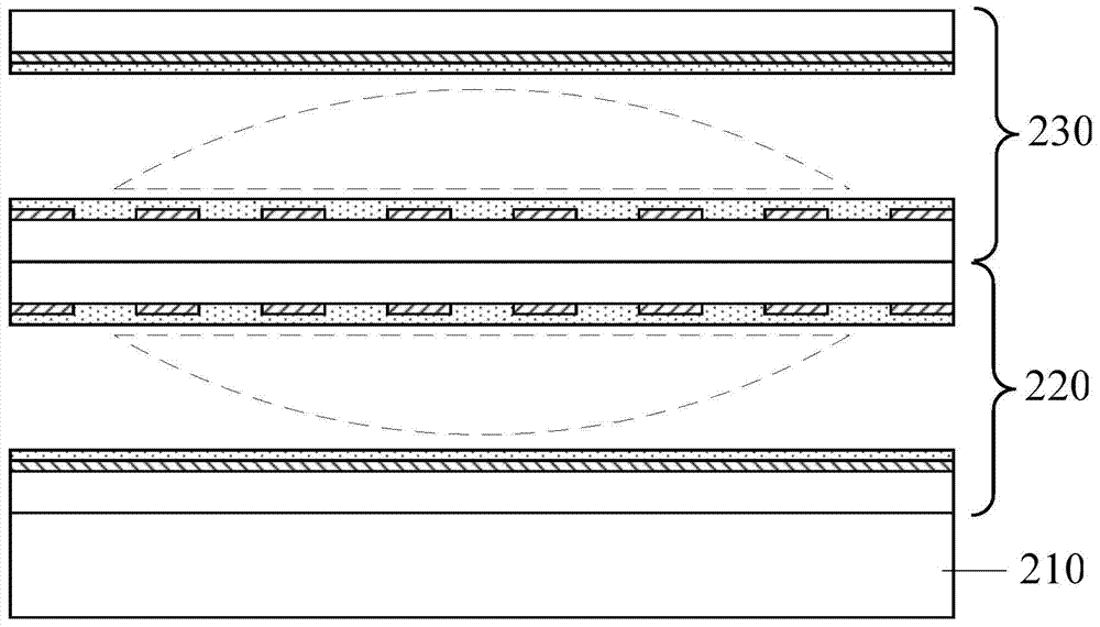
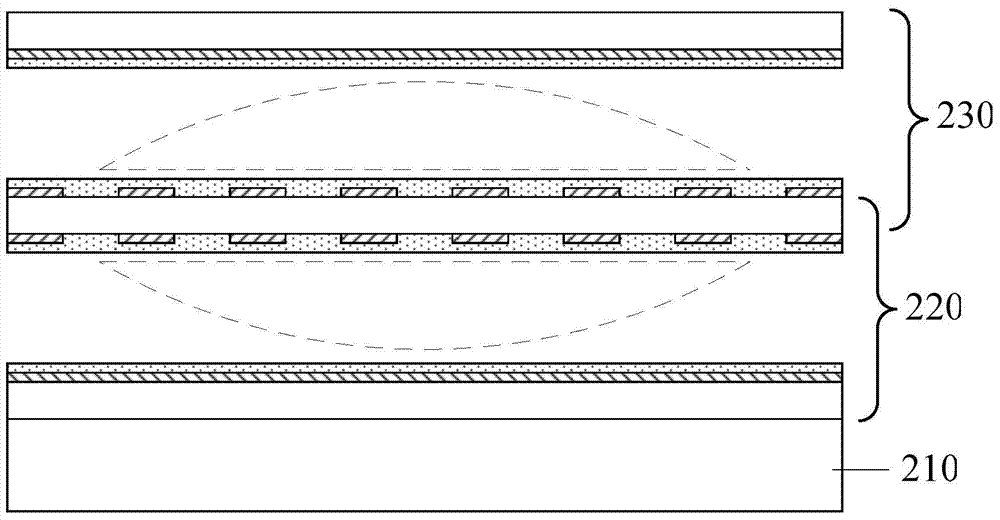
[0026] Such as figure 2 As shown, the 3D display device provided by an embodiment of the present invention includes a 2D display panel 210, and further includes: two liquid crystal gratings sequentially formed on the viewing side of the 2D display panel 210: a first liquid crystal grating 220 and a second liquid crystal grating 230 . In this embodiment, the sides where the respective strip electrodes of the two liquid crystal gratings are located face to face, so that the liquid crystals in the first liquid crystal grating 220 form the plane of the first plano-convex lens upward, and the liquid crystals in the second liquid crystal grating 230 form the second flat surfac...


PUM

PropertyMeasurementUnit
Box thicknessaaaaaaaaaa

Abstract

The invention discloses a 3D display device which comprises a 2D display panel and further comprises at least two liquid crystal gratings formed on an observing side of the 2D display panel in sequence. Each liquid crystal grating is used for forming a planoconvex lens, and then a planoconvex lens set is further formed. According to the 3D display device, at least two liquid crystal gratings are formed on the observing side of the 2D display panel, liquid crystal layers of at least two liquid crystal gratings can respectively form one planoconvex lens through control, the curvature of cambered surfaces of at least two planoconvex lenses can be controlled, aberration generated by one planoconvex lens is reduced, crosstalk caused by the liquid crystal gratings is relieved, and a display effect is improved.

Description

technical field [0001] The present invention relates to the technical field of 3D display, in particular to a 3D display device. Background technique [0002] An existing 3D display device includes a 2D display screen and a grating formed on the viewing side surface thereof. One of the gratings is a liquid crystal grating formed by a liquid crystal cell, such as figure 1 As shown, it includes: a first substrate 110 , a second substrate 120 , strip electrodes 130 , a first alignment layer 140 , block electrodes 150 , a second alignment layer 160 and a liquid crystal layer 170 . The strip electrodes 130 and the first alignment layer 140 are sequentially located on the first substrate 1, the block electrodes 150 and the second alignment layer 160 are sequentially located on the second substrate 120, and the liquid crystal layer 170 is located on the first alignment layer 140 and the second alignment layer. Between 160. Control the voltage of the strip electrodes 130 and bloc...

Claims


Application Information

Patent Timeline
IPC IPC(8): G02B27/22G02F1/13
Inventor 王海燕魏伟
Owner BOE TECH GRP CO LTD
Learn More