Rotor for an electric switch

A technology of electrical switches and rotors, used in electrical switches, electromagnetic release switches, circuit breakers with excessive current, etc.

Active Publication Date: 2014-03-26
SIEMENS AG
View PDF5 Cites 6 Cited by
  • Summary
  • Abstract
  • Description
  • Claims
  • Application Information

AI Technical Summary

Problems solved by technology

This asymmetry results in different contact forces and contact resistances at the contact locations

Method used


Image

  • Rotor for an electric switch
  • Rotor for an electric switch
  • Rotor for an electric switch

Examples


Embodiment Construction

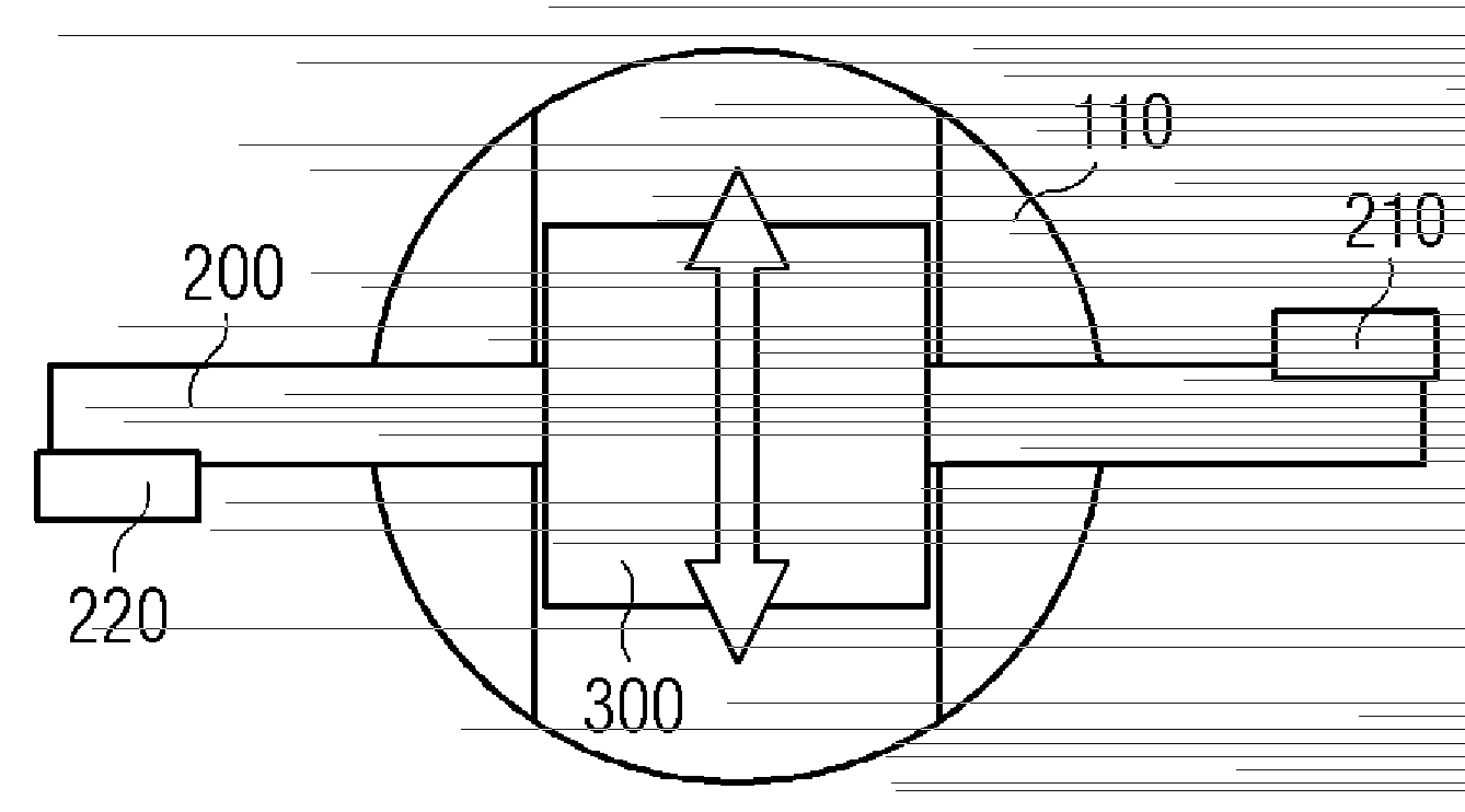
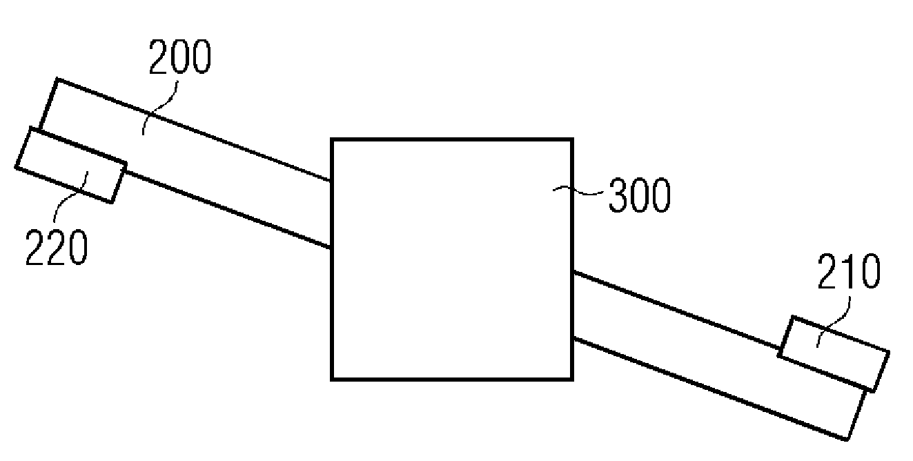
[0030] exist Figure 1A , 1B A rotor housing 110 for an electrical switch and a rotatably mounted contact bridge 200 comprising two movable contacts 210 , 220 are shown in and 1C. By rotating the rotor or the rotor housing 110 , the two movable contacts 210 , 220 can interact with the two fixed contacts of the electrical switch to close or open an electrical circuit. The rotatably mounted contact bridge 200 is mounted movably in the rotor housing 110 in a direction perpendicular to the direction of the contact bridge 200 in its closed position. according to Figure 1C , which means that the rotatably mounted contact bridge 200 is arranged movably in the direction of the arrow in the rotor housing 110 .

[0031] The rotatably mounted contact bridge 200 can be mounted in a suspension 300 which is in turn mounted movably in the rotor housing 110 .

[0032] The rotatably mounted contact bridge 200 is likewise mounted movably in the rotor housing 110 in a direction perpendicular...


PUM


Abstract

A rotor for an electric switch is disclosed. In an embodiment, the rotor includes a rotor housing and a rotatably mounted contact bridge, which exhibits two movable contacts, wherein, by the rotation of the rotor, the two movable contacts can interact with two fixed contacts of an electric switch for closing or opening a circuit. The rotatably mounted contact bridge in the rotor housing is movably mounted in a direction perpendicular to the direction of the contact bridge in its closed position.

Description

technical field [0001] The invention relates to a rotor for an electrical switch. Background technique [0002] Switching devices for switching electrical circuits typically comprise at least one contact system and further housing structures. The contact system forms an electrical switch and serves to switch current. One type of switching device is the so-called "circuit breaker", which typically switches 100A and more. The circuit breaker includes a housing in which individual phases of electrical current are switched. The individual phases of the current can be placed in a pole box, which is enclosed by its own housing. Arranged in the pole box are moving and stationary contacts, which can be mechanically separated or joined together for breaking or making current. When the pole box moves and the stationary contacts separate, an arc is formed which is typically extinguished in a so-called "interrupter". A circuit breaker is also disclosed which does not comprise a pol...

Claims


Application Information

Patent Timeline
Patent Type & Authority Applications(China)
IPC IPC(8): H01H71/10H01H73/04H01H73/38
CPCH01H1/2041H01H1/205H01H73/045H01H19/36
Inventor P.比东基维奇J-U.达尔C.韦伯
Owner SIEMENS AG
Why Eureka
Try Eureka