
A Wiring Structure Convenient for Battery Charging and Discharging Maintenance

A wiring structure and storage battery technology, applied in the electrical field, can solve problems that affect people's normal production and life, wrongly connect electrical wires, and related system paralysis, and achieve the effects of easy implementation and promotion, convenient maintenance, and avoiding adverse effects

Active Publication Date: 2016-08-10
JIYUAN POWER SUPPLY COMPANY OF STATE GRID HENAN ELECTRIC POWER
View PDF3 Cites 0 Cited by
  • Summary
  • Abstract
  • Description
  • Claims
  • Application Information

AI Technical Summary

Problems solved by technology

Now the wires of electrical appliances are directly connected to the battery. When maintaining the battery, the electrical wires must be removed from the battery terminals first, and a special person should record the corresponding relationship between the electrical wires and the battery terminals, and then another One person connects the detection connector to the battery terminal. The whole process requires two people to operate. Not only is the operation very inconvenient, time-consuming and laborious, but also it is easy to connect the wrong electrical wire and battery terminal due to the carelessness or mistake of the recorder, which will cause damage to the battery. Safety accidents lead to the paralysis of related systems, seriously affecting people's normal production and life

Method used


Image

  • A Wiring Structure Convenient for Battery Charging and Discharging Maintenance
  • A Wiring Structure Convenient for Battery Charging and Discharging Maintenance
  • A Wiring Structure Convenient for Battery Charging and Discharging Maintenance

Examples


Embodiment 1

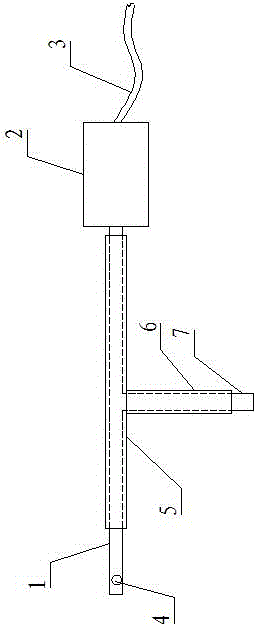
[0025] Such as figure 1 As shown, a wiring structure convenient for battery charge and discharge maintenance, it includes an electrode plate-1, one end of the electrode plate-1 is provided with a connection hole 4 for connecting with the battery terminal, and the other end of the electrode plate-1 A switch 2 is connected, and the switch 2 is connected with a wire 3 connected with an electrical appliance.

[0026] When the present invention is in use, first disconnect the wire from the electrode plate 1 by disconnecting the switch, and then connect the detection joint to the electrode plate 1. After the detection and maintenance are completed, remove the detection joint and close the switch to conduct the wire and the electrode plate One connection solves the traditional problems of requiring two people, time-consuming and laborious operation, inconvenient operation, and potential safety hazards. Only one person is needed to complete the operation, which is convenient and quick...

Embodiment 2

[0028] Such as figure 2 As shown, a wiring structure convenient for battery charge and discharge maintenance, it includes an electrode plate-1, one end of the electrode plate-1 is provided with a connection hole 4 for connecting with the battery terminal, and the other end of the electrode plate-1 A switch 2 is connected, and the switch 2 is connected with a wire 3 connected with an electrical appliance.

[0029] An insulating layer 5 is provided on the outer side of the electrode plate 1 between the connection hole 4 and the switch 2 .

[0030] The insulating layer one 5 is an insulating material sprayed on the outside of the electrode plate one 1 or an insulating sleeve sleeved on the outside of the electrode plate one 1 .

[0031] The middle part of the insulating layer 5 is provided with a notch 5-1 exposing the electrode plate 5. The notch 5-1 is distributed along the radial direction of the electrode plate 1 and divides the insulating layer 5 into two sections.

[003...

Embodiment 3

[0035] Such as image 3 As shown, a wiring structure convenient for battery charge and discharge maintenance, it includes an electrode plate-1, one end of the electrode plate-1 is provided with a connection hole 4 for connecting with the battery terminal, and the other end of the electrode plate-1 A switch 2 is connected, and the switch 2 is connected with a wire 3 connected with an electrical appliance.

[0036] An insulating layer 5 is provided on the outer side of the electrode plate 1 between the connection hole 4 and the switch 2 .

[0037] The insulating layer one 5 is an insulating material sprayed on the outside of the electrode plate one 1 or an insulating sleeve sleeved on the outside of the electrode plate one 1 .

[0038] The middle part of the insulating layer 5 is provided with a notch 5-1 exposing the electrode plate 5. The notch 5-1 is distributed along the radial direction of the electrode plate 1 and divides the insulating layer 5 into two sections.

[0039...


PUM

PropertyMeasurementUnit
lengthaaaaaaaaaa

Abstract

The invention relates to a wiring structure for convenient battery charge and discharge maintenance, which includes an electrode plate 1, one end of the electrode plate 1 is provided with a connection hole for connecting with a battery terminal, and the other end of the electrode plate 1 is connected with a switch. The switch is connected with a wire connected to the electrical appliance; when the present invention is in use, the connection between the wire and the electrode plate 1 is first disconnected by disconnecting the switch, and then the detection joint is connected to the electrode plate 1. After the detection and maintenance are completed, the detection The joint closure switch is the connection between the conductive wire and the electrode plate 1, which solves the traditional problems of requiring two people, time-consuming and laborious, inconvenient operation, and potential safety hazards. It has a simple structure, is easy to implement and popularize, and only needs one person to complete the operation. , The advantages of convenient and quick use, time-saving and labor-saving.

Description

technical field [0001] The invention relates to the field of electrical technology, in particular to a wiring structure, in particular to a wiring structure that is convenient for battery charge and discharge maintenance. Background technique [0002] A storage battery is a device that directly converts chemical energy into electrical energy. It is a rechargeable battery designed to be recharged through a reversible chemical reaction and belongs to a secondary battery. Its working principle: when charging, the external electric energy is used to regenerate the internal active material, the electric energy is stored as chemical energy, and the chemical energy is converted into electric energy output again when it needs to be discharged. Batteries are widely used in power systems. After many times of charging and discharging, the battery will have a phenomenon of power decline. In order to prolong the service life of the battery and maintain the good working condition of the b...

Claims


Application Information

Patent Timeline
Patent Type & Authority Patents(China)
IPC IPC(8): H01M2/20H01M50/502
CPCH01M10/4285Y02E60/10
Inventor 苗堃范争争白继武赵倩李颂刘晶晶孔小利郭会丽李小红
Owner JIYUAN POWER SUPPLY COMPANY OF STATE GRID HENAN ELECTRIC POWER
Learn More