Novel box-type transformer substation

A box-type substation, a new type of technology

Inactive Publication Date: 2014-03-26
蒋计
View PDF6 Cites 1 Cited by
  • Summary
  • Abstract
  • Description
  • Claims
  • Application Information

AI Technical Summary

Problems solved by technology

The defect in the use of this existing box-type substation room is that the heat dissipation of the substation depends on the operation of the electric fan or fan installed in the room to ventilate and dissipate heat, so it needs to consume electric energy and waste energy.
Irregular maintenance of running electric fans or blowers will increase maintenance costs and workload of maintenance workers
Moreover, when the existing box-type substation is working, the internal instruments will generate a lot of noise, which will have a great impact on the surrounding residents. Moreover, the box-type substation is often exposed to the sun, and the internal temperature of the box-type transformer will rise, which will affect the box-type substation. In serious cases, it will cause the circuit breaker to trip frequently, and even cause the transformer to explode, which directly affects the work and life of the masses.
[0005] Moreover, the shell of the existing box-type substation is not equipped with lighting facilities, so that pedestrians or vehicles without lights hit the shell of the substation in the dark, causing accidents and heavy losses
[0006] The box-type substation in the above-mentioned prior art cannot be naturally ventilated, and the fans inside the box-type substation are used to dissipate heat, and the fan needs to be repaired irregularly, which consumes electric energy, wastes resources, and increases maintenance costs and the work of maintenance workers. It cannot effectively isolate the external heat of the box-type substation from being transmitted to the substation, nor can it isolate the large amount of noise generated by the instruments inside the substation from being transmitted to the outside of the substation, and the existing substation shell is not equipped with bright facilities. As a result, pedestrians or vehicles without lighting equipment hit the substation in the dark, causing accidents and heavy losses

Method used


Image

  • Novel box-type transformer substation
  • Novel box-type transformer substation
  • Novel box-type transformer substation

Examples


Embodiment 1

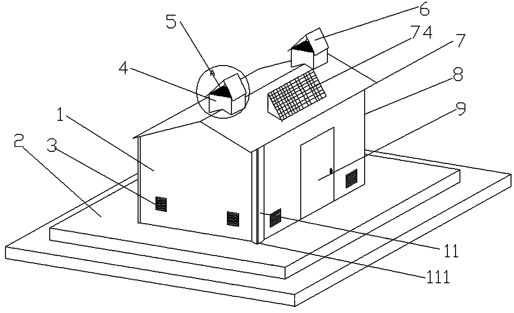
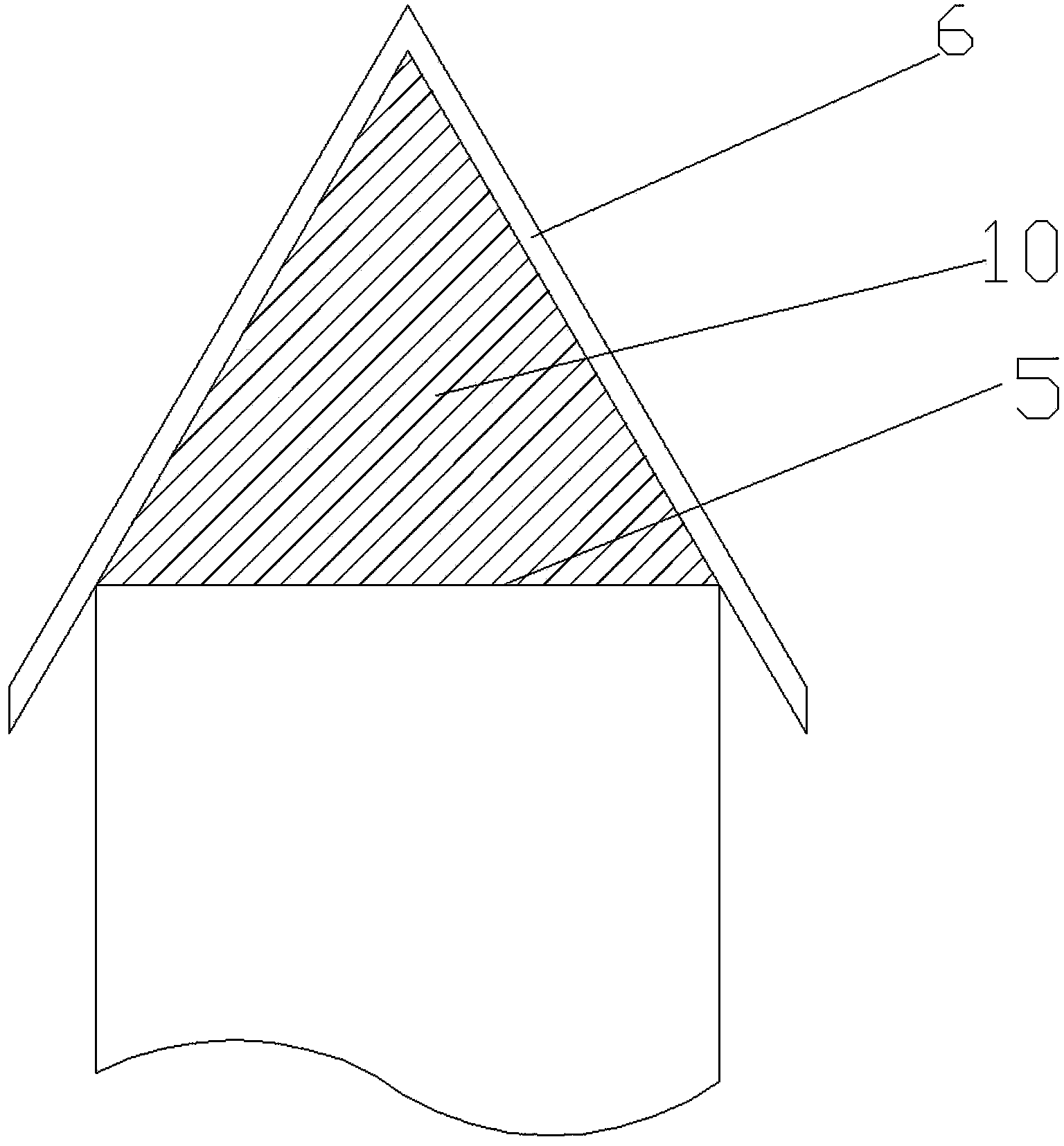
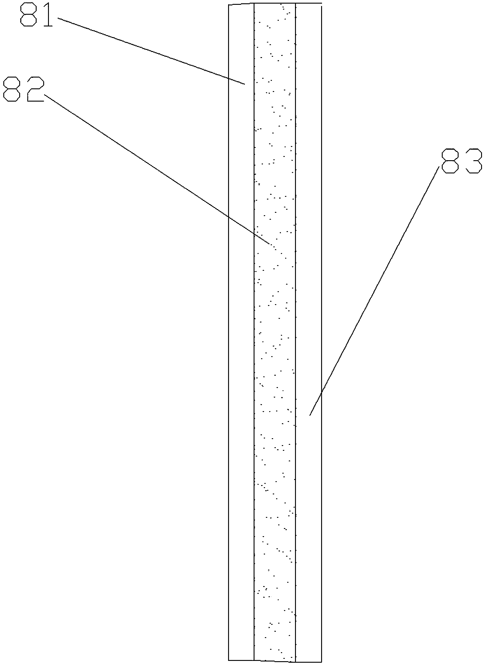
[0033] As a preferred embodiment of the present invention, the present invention includes a box body 1 and a base 2, and the box body 1 is composed of a column 11 around, a wall plate 8, a door 9 and a slope-shaped cover plate 7 at the top, and is characterized in that : the top of the slope-shaped cover plate 7 is provided with at least one column vent 4, the column vent 4 protrudes from the slope-shaped cover plate 7, and a layer of gauze 5 is arranged on the column vent 4, Described column air vent 4 is also provided with rain shielding plate 6, and stainless steel wire mesh 10 is housed between described rain shielding plate 6, and described stainless steel wire mesh 10 is fixed on rain shielding plate 6 both sides by screw. The wall board 8 is composed of an outer wall board 83, a vacuum board 82 and an inner wall board 81, the vacuum board 82 is bonded between the outer wall board 83 and the inner wall board 81, and a solar controller is also installed on the inner wall b...

Embodiment 2

[0039] As another preferred embodiment of the present invention, the present invention includes a box body 1 and a base 2. The box body 1 is composed of columns 11 around, wall panels 8, doors 9 and slope-shaped cover plates 7 at the top. In that: the top of the slope-shaped cover plate 7 is provided with at least one column vent 4, the column vent 4 protrudes from the slope-shaped cover plate 7, and a layer of gauze 5 is arranged on the column vent 4 , said column air vent 4 is also provided with a rain shield 6, stainless steel wire mesh 10 is housed between said rain shield 6, and said stainless steel wire mesh 10 is fixed on both sides of the rain shield 6 by screws. The wall board 8 is composed of an outer wall board 83, a vacuum board 82 and an inner wall board 81, the vacuum board 82 is bonded between the outer wall board 83 and the inner wall board 81, and a solar controller is also installed on the inner wall board 81 84 and accumulator 85; described slope cover plate...

Embodiment 3

[0046] As another preferred embodiment of the present invention, the present invention includes a box body 1 and a base 2. The box body 1 is composed of columns 11 around, wall panels 8, doors 9 and slope-shaped cover plates 7 at the top. In that: the top of the slope-shaped cover plate 7 is provided with at least one column vent 4, the column vent 4 protrudes from the slope-shaped cover plate 7, and a layer of gauze 5 is arranged on the column vent 4 , said column air vent 4 is also provided with a rain shield 6, stainless steel wire mesh 10 is housed between said rain shield 6, and said stainless steel wire mesh 10 is fixed on both sides of the rain shield 6 by screws. The wall board 8 is composed of an outer wall board 83, a vacuum board 82 and an inner wall board 81, the vacuum board 82 is bonded between the outer wall board 83 and the inner wall board 81, and a solar controller is also installed on the inner wall board 81 84 and accumulator 85; described slope cover plate...


PUM


Abstract

The invention discloses a novel box-type transformer substation, and relates to the technical field of transformer substations. The novel box-type transformer substation comprises a box and a base. The box comprises peripheral upright columns, wall plates, a door and top slope-shaped cover plates. The novel box-type transformer substation is characterized in that at least one upright column ventilation opening is formed in the top of each slope-shaped cover plate. The novel box-type transformer substation has the advantages that the novel box-type transformer substation is high in ventilation efficiency, and a natural ventilation effect can be completely realized without the aid of other instruments; external heat can be effectively stopped from being transmitted into the box-type transformer substation, and a large quantity of noise generated by instruments in the box-type transformer substation can be effectively stopped from being transmitted to the outside of the box-type transformer substation; illuminating warning equipment is provided at night on the basis that an occupied space of the original box-type transformer substation is not enlarged, and the novel box-type transformer substation is attractive in appearance and simple in structure.

Description

technical field [0001] The invention relates to the technical field of substations, in particular to a novel box-type substation. Background technique [0002] With the rapid development of economic construction and the acceleration of my country's urbanization process, various commercial buildings, public supporting buildings and residential buildings continue to emerge all over the country; box-type substations, as supporting power facilities, have been widely used in various places. [0003] Box-type substation is a kind of high-voltage switchgear, distribution transformer and low-voltage power distribution device. It is a factory prefabricated indoor and outdoor compact power distribution equipment arranged according to a certain wiring scheme. It is about high-voltage power receiving, transformer step-down, low-voltage distribution Electricity and other functions are organically combined and installed in a moisture-proof, rust-proof, rodent-proof, fire-proof, anti-theft...

Claims


Application Information

Patent Timeline
IPC IPC(8): H02B1/56H02B1/28H02B1/26
Inventor 蒋计
Owner 蒋计
Why Eureka
Try Eureka