
Sanding equipment for furniture part

A technology for sanding and parts, applied in the field of furniture manufacturing, can solve the problems of cumbersome operation, low work efficiency, single processing object, etc., and achieve the effect of reducing technical requirements, improving processing efficiency, and improving processing environment

Inactive Publication Date: 2014-04-02
中山市锋凡机械设备有限公司
View PDF10 Cites 20 Cited by
  • Summary
  • Abstract
  • Description
  • Claims
  • Application Information

AI Technical Summary

Problems solved by technology

However, this type of polishing machine still fails to meet the requirements of today's furniture manufacturing industry, specifically as follows:
[0004] 1. There are strict requirements on the shape of furniture parts, only the flat surface of furniture parts can be processed, and furniture parts with curved surfaces cannot be polished, and the processing method is not flexible enough;
[0005] 2. The polishing machine is designed by a single-chip microcomputer for furniture parts of a certain specification. Generally, it cannot process furniture parts of other specifications, and the processing object is relatively single;
[0006] 3. When the thickness of furniture parts changes, it is necessary to manually adjust the position of the sanding head. The operation is cumbersome and requires someone to track the whole process, and the work efficiency is low.

Method used


Image

  • Sanding equipment for furniture part
  • Sanding equipment for furniture part
  • Sanding equipment for furniture part

Examples


Embodiment Construction

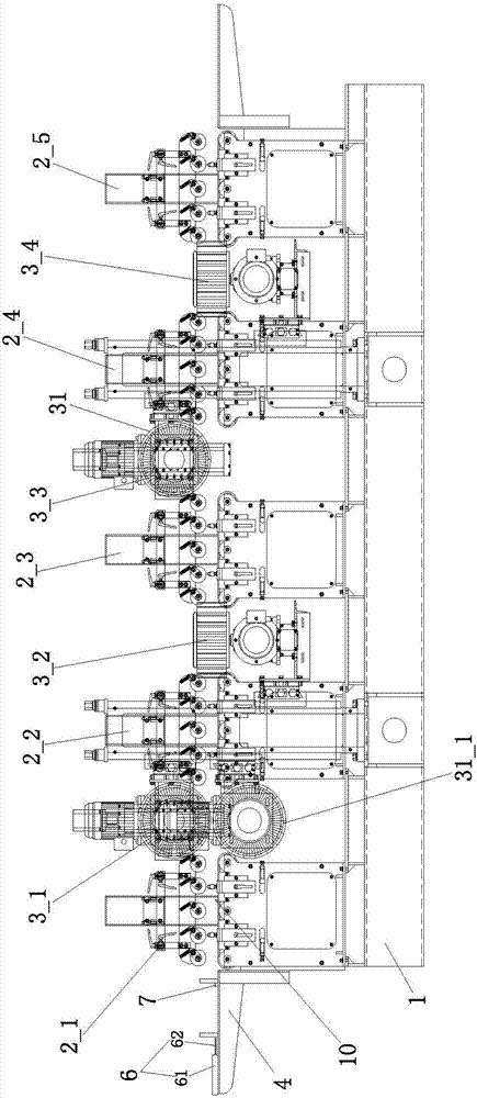
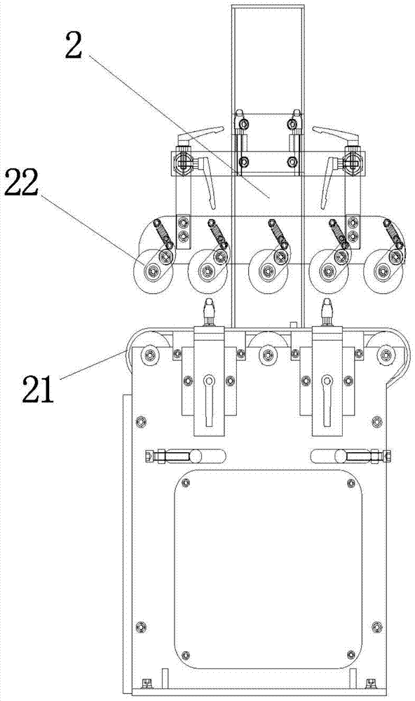
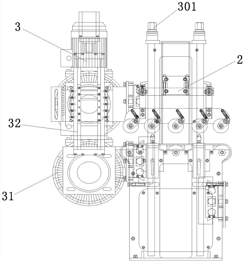
[0046] As a preferred embodiment of the present invention, in conjunction with the attached Figure 1-3 , the described sanding equipment for furniture parts includes:

[0047] The conveying device 2 includes a conveying belt 21 for conveying furniture parts along the conveying direction;

[0048] A sanding device 3, including a sander 31, for polishing at least one surface of a furniture part;

[0049] The feeding platform 4 is arranged on the upstream of the conveying device 2, and is used to carry the above-mentioned furniture parts and send them to the conveying device 2; and

[0050] A control device connected to the conveying device 2 and the sanding device 3 to control the conveying device 2 and the sanding device 3;

[0051]The conveying device 2 also includes a conveying pressure wheel 22 arranged above the conveying belt 21, and the conveying pressure roller 22 and the conveying belt 21 clamp the furniture parts and transmit them along the conveying direction;

[...


PUM


Abstract

The invention provides sanding equipment for a furniture part, which has the advantages of flexible machining way, high accuracy and the like. The sanding equipment comprises conveying devices, sanding devices, a feeding platform and a control device, which are arranged on a base. The sanding equipment is characterized in that each conveying device comprises a conveying belt and conveying pressure rollers arranged above the conveying belt; each sanding device comprises a sand grinder and a moving mechanism which is arranged in parallel or vertical to a conveying device; each sand grinder is fixedly arranged on each moving mechanism, and can move forwards and backwards along a conveying direction or ascends and descends vertical to the conveying direction along with the moving mechanism; the sanding equipment at least comprises two conveying devices and one sanding device; any sanding device is positioned between the two conveying devices; the size information of the furniture part is at least stored or can be acquired from the control device, and the size information is translated to generate the running parameters of the conveying devices and the sanding devices; the sanding equipment comprises at least one sensing switch for acquiring the origin information of the furniture part.

Description

[0001] technical field [0002] The invention relates to the field of furniture manufacturing, in particular to a sanding device for furniture parts. Background technique [0003] The polishing process of traditional furniture parts has always been done manually, and its disadvantages are obvious: large labor demand, high processing intensity, harsh environment and low processing efficiency. In order to change the above situation, some large-scale polishing machines capable of batch processing have also appeared at present, which generally include a frame, a feeding line passing through the frame, and sand mills located above or on both sides of the feeding line. During processing, the furniture parts are sent by the feeding line through sanding, and the sanding process polishes the top surface or both sides of the furniture parts. However, this type of polishing machine still fails to meet the requirements of today's furniture manufacturing industry, specifically as follow...

Claims


Application Information

Patent Timeline
Patent Type & Authority Applications(China)
IPC IPC(8): B24B19/24
CPCB24B19/24B24B55/06
Inventor 陶熔
Owner 中山市锋凡机械设备有限公司
Learn More