Flat Section Zigzag Cut Wire

A technology for cutting steel wire and zigzag, which is applied in the field of flat cross-section zigzag cutting wire, which can solve the problems of poor ability to carry abrasives, low tensile strength, and low cutting efficiency of silicon crystal by cutting wire

Active Publication Date: 2015-12-23
苏闽(张家港)新型金属材料科技有限公司
View PDF8 Cites 3 Cited by
  • Summary
  • Abstract
  • Description
  • Claims
  • Application Information

AI Technical Summary

Problems solved by technology

[0003] In the Chinese utility model patent application with the application number 201020643955.6 and the application date being December 6, 2010, "a special-shaped cutting steel wire" is disclosed. The problem of low hardness and tensile strength, but this kind of cutting wire is flat and straight along the axial direction, not only in the process of cutting silicon crystals, it slips seriously, but this kind of flat and straight cutting wire has a high degree of stability in the process of cutting silicon crystals. Poor ability to carry abrasives, resulting in inefficient wire cutting
[0004] In the Chinese utility model patent application with the application number 201020644391.8 and the application date on December 6, 2010, "a kind of corrugated special-shaped cutting steel wire" is disclosed, because the cross section of the cutting steel wire is processed to be circular or approximately circular In this way, in the process of cutting the silicon crystal, the cutting wire is easy to rotate in the guide groove of the main roller along its own axis, and the cutting wire that rotates in the guide groove of the main roller will drive the abrasive to the silicon crystal. The cutting surface is scratched, thereby leaving scratches or line marks on the cutting surface of the silicon crystal, resulting in poor surface finish of the cutting surface of the silicon crystal, thereby reducing the photoelectric conversion efficiency of the silicon wafer after cutting; and, due to this A wavy special-shaped cutting wire is processed into a wavy structure with a smooth transition along the axial direction, and the cutting efficiency of this smooth transition cutting wire for silicon crystals is low

Method used


Image

  • Flat Section Zigzag Cut Wire
  • Flat Section Zigzag Cut Wire
  • Flat Section Zigzag Cut Wire

Examples


Embodiment Construction

[0013] The present invention will be further described below in conjunction with the accompanying drawings and specific embodiments.

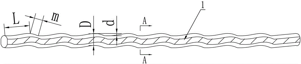
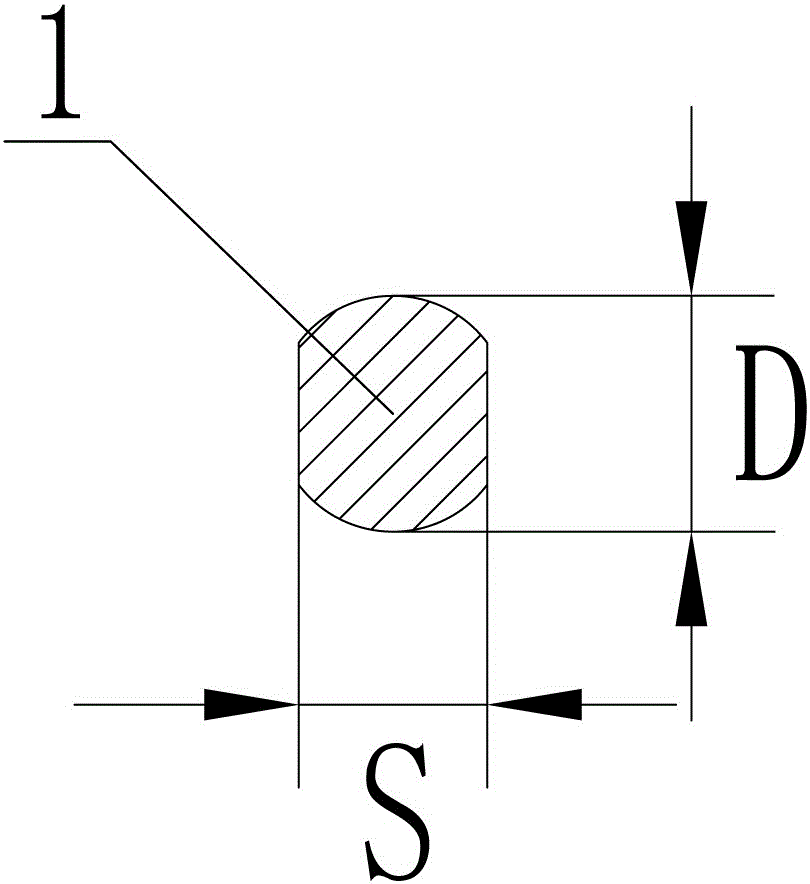
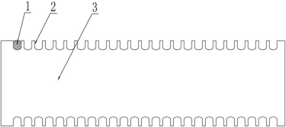
[0014] Such as figure 1 , figure 2 , image 3 As shown, the flat section zigzag cutting steel wire includes: cutting steel wire 1, the cross section of the cutting steel wire 1 is set in a flat shape, the cutting steel wire 1 is continuously zigzag distributed along its axial direction, and the sawtooth in the cutting steel wire 1 The length of the short side m of the sawtooth is 1 / 3 to 1 / 2 times the length of the long side L of the sawtooth, and the height d of the sawtooth is 0.15 to 0.3 times the height D of the flat cross-section of the cutting steel wire 1. The setting of the sawtooth It can effectively increase the feeding speed of the silicon rod when the cutting steel wire 1 cuts silicon crystals, and further improves the cutting efficiency of the cutting steel wire 1 for silicon crystals; the ratio of the width S to the height D of ...


PUM


Abstract

The invention discloses a sawtooth-shaped cutting steel wire with a flat section. The sawtooth-shaped cutting steel wire comprises a cutting steel wire body, wherein the cross section of the cutting steel wire body is flat; the cutting steel wire body is in continuous sawtooth-shaped distribution along the axial direction; the length of a short sawtooth edge of each sawtooth in the cutting steel wire body is 1 / 3-1 / 2 time of the length of a long sawtooth edge of each sawtooth; the height of each sawtooth is 0.15-0.3 time of the height of the flat cross section of the cutting steel wire body; a ratio of the width to the height of the flat cross section of the cutting steel wire body is 0.7-0.9. The sawtooth-shaped cutting steel wire with the flat section has the advantages that due to the flat arrangement of the cross section of the cutting steel wire, the phenomenon of self-rotation of the cutting steel wire in a main roller guide slot in a cutting process is avoided; line marks on the tail part of a silicon crystal cutting surface are reduced, the surface smoothness of the silicon crystal cutting surface is improved, and the cutting stability of the cutting steel wire is further improved; furthermore, due to the continuous and uniform sawtooth-shaped arrangement of the cutting steel wire along the axial direction, the silicon stick feeding speed of the cutting steel wire is increased, and the cutting efficiency is improved.

Description

technical field [0001] The invention relates to a flat cross-section zigzag cutting steel wire for cutting hard and brittle materials such as silicon crystals. Background technique [0002] In the division and slicing process of hard and brittle materials such as silicon crystals in the fields of electronics and solar energy, metal monofilaments, commonly known as cutting wires, are generally wound in the guide grooves of several main rollers in sequence, and then the main rollers are rotated. Drive the cutting steel wire to reciprocate, so that the abrasive with extremely high hardness is brought into the cutting port through the reciprocating motion of the cutting steel wire, and the abrasive continuously grinds the silicon crystal under the reciprocating motion of the metal monofilament, thereby realizing the cutting and slicing of the silicon crystal . At present, the smoothness performance of the cut surface of the silicon wafer is mainly determined by the performance ...

Claims


Application Information

Patent Timeline
Patent Type & Authority Patents(China)
IPC IPC(8): B28D5/04
Inventor 吴晓玲
Owner 苏闽(张家港)新型金属材料科技有限公司
Why Eureka
Try Eureka