Uniform type braking force balancing device and method of magnetic track brakes on both sides of rail train

A technology of magnetic rail brakes and rail trains, which is applied in the direction of brakes interacting between brake elements and rails, railway braking systems, transportation and packaging, etc., to achieve improved braking safety, improved efficiency and reliability, and reliable performance Effect

Active Publication Date: 2014-04-02
中航安贞(浙江)信息科技有限公司
View PDF7 Cites 7 Cited by
  • Summary
  • Abstract
  • Description
  • Claims
  • Application Information

AI Technical Summary

Problems solved by technology

[0004] The purpose of the present invention is to solve the problems existing in the operation of the existing magnetic rail brakes, and propose a braking force balance device for the magnetic rail brakes on both sides of the uniform track train, which provides balanced braking force for the magnetic rail brakes on both sides of the train, so that The train does not brake and deviate to ensure the safety of the train; the invention also proposes a braking force balancing method of the braking force balancing device, which can effectively adjust the braking force of the magnetic rail brake and improve the efficiency and reliability of the magnetic rail brake

Method used


Image

  • Uniform type braking force balancing device and method of magnetic track brakes on both sides of rail train
  • Uniform type braking force balancing device and method of magnetic track brakes on both sides of rail train
  • Uniform type braking force balancing device and method of magnetic track brakes on both sides of rail train

Examples


Embodiment Construction

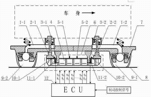
[0015] figure 1 In , the direction indicated by the arrow on the train body is the front. Below the bottom of the train body is a horizontally arranged bogie 7, and frames are installed on the left and right sides of the bogie 7, that is, both sides of the train bogie, and the frames on both sides of the train are symmetrical. The two frames on the same side are respectively the rear frame 1-1 and the front frame 1-2, and the rear frame 1-1 and the front frame 1-2 are all located on the same side of the front wheel 9-1 and the rear wheel 9- 2, the rear frame 1-1 is close to the rear wheel 9-2, the front frame 1-2 is close to the front wheel 9-1, and the rear frame 1-1 and the front frame 1-2 are relatively to the front wheel 9- 1 and the middle position between the rear wheel 9-2 are symmetrical front and back. Both the rear frame 1-1 and the front frame 1-2 are fixedly welded together with the bogie 7.

[0016] At the front part of the rear frame 1-1, a rear brake suspen...


PUM


Abstract

The invention discloses a uniform type braking force balancing device and method of magnetic track brakes on both sides of a rail train. According to the uniform type braking force balancing device and method of the magnetic track brakes on both sides of the rail train, a front pressure sensor and a rear pressure sensor are arranged between force transmission boards of the magnetic track brakes and a force transmission column of a train steering rack; each magnetic brake is provided with six iron cores, and every iron core is wound with three coils; the rear end of the first coil of every iron core is directly connected with the negative electrode of storage batteries, the front end of the first coil of every iron core is connected with the positive electrode of the storage batteries through switches K4 and K1; the rear end of the second coil of every iron core is directly connected with the negative electrode of the storage batteries, and the front end of the second coil of every iron core is connected with the positive electrode of the storage batteries through switches K3 and K1; the front end of the third coil of every iron core is connected with the positive electrode of the storage batteries through switches K2 and K1, and the rear ends of the third coils of the six iron cores are connected with the negative electrode of the storage batteries through switches K5, K6, K7, K8, K9 and K10 respectively. The uniform type braking force balancing device and method of the magnetic track brakes on both sides of the rail train can effectively avoid brake deviation of the train due to the fact that the magnetic track brakes on both sides of the same steering rack generate overlarge brake force difference in different gear positions, and accordingly improves the braking safety of the rail train.

Description

technical field [0001] The invention belongs to the technical field of rail vehicle braking and safety, and relates to a braking force balancing device for magnetic rail brakes on both sides of rail trains. Background technique [0002] For trains using magnetic rail braking, a horizontal bogie is arranged under the bottom of the train body. There is a frame between the front and rear wheels on the same side of the train bogie. The bogie and the frame are fixed together by welding. On the frame Fix the brake suspension device, and hang the magnetic track brake under the brake suspension device. The magnetic track brake is located on the upper part of the train track, parallel to the track and arranged longitudinally along the front and rear of the track. There is a gap between them. Described magnetic rail brake generally has a plurality of electromagnets, and a plurality of electromagnets are distributed at equal intervals directly above the track and along the longitudin...

Claims


Application Information

Patent Timeline
Patent Type & Authority Applications(China)
IPC IPC(8): B61H7/08
Inventor 陈士安杨鑫游专姚明彭佳鑫马银张晓娜武晓晖
Owner 中航安贞(浙江)信息科技有限公司
Why Eureka
Try Eureka