Vibration isolator outer sleeve

A technology of vibration isolators and outer sleeves, which is applied in roads, tracks, buildings, etc., can solve the problems of many welding points, inconvenient operation, inconvenient use, etc., to achieve increased supporting area, easy installation and operation, and not easy to damage Effect

Active Publication Date: 2014-04-02
易科路通轨道设备有限公司
View PDF8 Cites 5 Cited by
  • Summary
  • Abstract
  • Description
  • Claims
  • Application Information

AI Technical Summary

Problems solved by technology

[0004] 1. Once the sleeve is installed, it cannot be replaced, and the jacking block 11 or support block 12 is fixed on the sleeve by welding. Welding is the weakest link of the sleeve, and it is difficult to guarantee the reliability in the long-term use process, and There are many welding points, it is difficult to ensure the accuracy of the height of the weldment and the welding strength of multiple weldments. Once damaged, it is difficult to repair, and even after repair, it is difficult to restore the original working state;
[0005] 2. The sleeve is generally made of steel plate, which requires reliable anti-corrosion treatment separately
[0006] A damping sleeve is disclosed in Chinese patent document CN201110336684.9, which still has disadvantages, such as a cylindrical shape with a protruding part, and a vibration isolator inside the sleeve After placement, there is not enough space for rotation, and the rotation direction of the rotation installation is single, which is inconvenient to operate; if the support hole is rectangular, the vibration isolator cannot limit the position; the support hole and the jacking hole are staggered, making it inconvenient to use; the jacking hole and The support hole is not equipped with an outer protective cover, which cannot prevent concrete from entering, and the bottom of the vibration isolator is not provided with a rotation space for the vibration isolator. It is required that the top cover of the vibration isolator must be movable or the outer diameter of the bottom of the vibration isolator must not be greater than the radius of the inner ring of the sleeve ; There is no external anchoring steel bar, so that the anchoring strength between the sleeve and concrete is insufficient

Method used


Image

  • Vibration isolator outer sleeve
  • Vibration isolator outer sleeve
  • Vibration isolator outer sleeve

Examples


Embodiment Construction

[0068] The present invention will be further described in detail through the drawings and examples below. From these descriptions, the features and advantages of the present invention will become more apparent.

[0069] The word "exemplary" is used exclusively herein to mean "serving as an example, embodiment, or illustration." Any embodiment described herein as "exemplary" is not necessarily to be construed as superior or better than other embodiments. While various aspects of the embodiments are shown in drawings, the drawings are not necessarily drawn to scale unless specifically indicated.

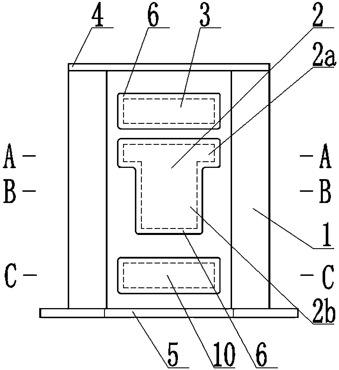
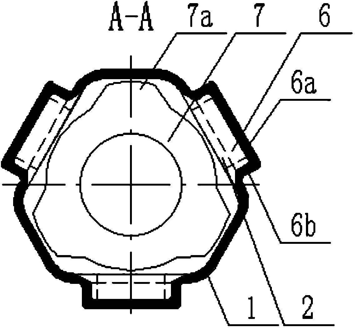
[0070] According to a preferred embodiment of the present invention, such as Figures 2 to 9 As shown in , the outer sleeve of the vibration isolator is provided. The sleeve includes a sleeve body 1. The sleeve body is a cylindrical structure with a unequal polygonal cross section. The length of the sleeve body corresponding to the long side of the polygon T-shaped support holes 2 a...


PUM


Abstract

The invention discloses a vibration isolator outer sleeve which comprises a sleeve body integrally formed. The cross section of the sleeve body is of a non-equilateral polygon cylindrical structure. T-shaped support holes are formed in the side walls, corresponding to at lest two relatively-long edges, of the sleeve body. Each T-shaped support hole comprises a horizontal hole extending towards two sides and a vertical hole extending downwards from the middle of the horizontal hole. A jacking hole is formed in the side wall, above each support hole, of the sleeve body. The outside of the sleeve body is provided with a boss extending outwardly from each support hole and the corresponding jacking hole. Each boss recesses towards one side of the center of the sleeve body to form a pit. The sleeve is simple in structure, integrally formed, good in mechanical performance, long in service life, convenient to operate and good in limit effect, no special limit parts are needed, and a vibration isolator can be rotated into the sleeve from two directions and limited by the T-shaped support holes.

Description

technical field [0001] The invention relates to a wheel-rail traffic and a vibration-reducing and noise-reducing track device, in particular to an outer sleeve of a vibration isolator. Background technique [0002] Spring vibration isolator is the most commonly used type of vibration isolator, made of steel spring or rubber. There are spiral, disc, ring and plate forms. Its advantages are: large static compression, low natural frequency, good low-frequency vibration isolation performance; can withstand oil, water, etc., and temperature changes do not affect performance; no aging, no creep, etc. In practical applications, insulation The outside of the vibrator is usually designed with a vibration isolator outer sleeve. [0003] In the prior art, the outer sleeve of the vibration isolator has a circular shape, and its jacking block and supporting block are all welded, such as figure 1 As shown, this technique has the following disadvantages: [0004] 1. Once the sleeve is ...

Claims


Application Information

Patent Timeline
Patent Type & Authority Applications(China)
IPC IPC(8): E01B19/00
Inventor 曾向荣任静李恒义李玉路李晶晶张笑方
Owner 易科路通轨道设备有限公司
Why Eureka
Try Eureka