Rotation-driven swing valve type continuous wave generator

A wave generator and rotary drive technology, applied in the field of continuous wave generators, can solve problems such as rotor jamming, achieve the effects of improving drilling safety, simple structure, and reducing the risk of jamming

Active Publication Date: 2014-04-02
BC P INC CHINA NAT PETROLEUM CORP +1
View PDF6 Cites 14 Cited by
  • Summary
  • Abstract
  • Description
  • Claims
  • Application Information

AI Technical Summary

Problems solved by technology

Compared with the shear valve continuous wave generator, the rotary valve continuous wave generator is unilaterally rotated, easy to adjust, and has low requirements on the motor, but it is prone to ro

Method used


Image

  • Rotation-driven swing valve type continuous wave generator
  • Rotation-driven swing valve type continuous wave generator
  • Rotation-driven swing valve type continuous wave generator

Examples


Embodiment Construction

[0043] The technical solution of the present invention will be further clearly and completely described below in conjunction with the accompanying drawings.

[0044] In the embodiments of the present invention, for the convenience of description, the relative positional relationship of each component is described according to the layout of the drawings in the description, for example: the upper and lower positional relationship is determined according to the layout of the parts in the drawings of the description .

[0045] Embodiments of the present invention will be further described below in conjunction with the accompanying drawings:

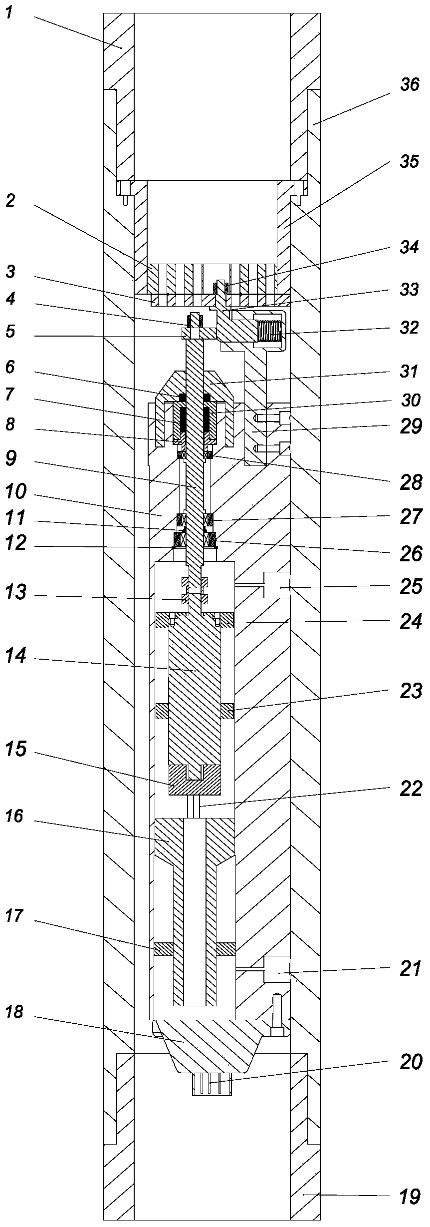
[0046] Such as figure 1 As shown, a shear valve continuous wave generator driven by rotation includes a drill collar 36 and a continuous wave generating unit installed in the drill collar 36, a rotation-swing conversion mechanism, a power output unit, a sealing module, and a pressure balance module and electrical connection modules.

[004...


PUM


Abstract

The invention discloses a rotation-driven swing valve type continuous wave generator comprising a drill collar, a continuous wave generating unit, a rotation-swinging conversion mechanism, a power output unit, a sealing module, a pressure balancing module and an electrical connection module. The continuous wave generating unit, the rotation-swinging conversion mechanism, the power output unit, the sealing module, the pressure balancing module and the electrical connection module are mounted in the drill collar. A drill collar inside mounting sleeve is mounted in the cavity of the drill collar eccentrically. The continuous wave generating unit comprises a stator mounting sleeve mounted at the upper center of the drill collar, a stator mounted at the bottom of the stator mounting sleeve and a swinger mounted below the stator and connected with the rotation-swinging conversion mechanism, and both the stator and the swinger are provided with throttling holes. The rotation-swinging conversion mechanism converts rotation motion output by the power output unit into transverse reciprocating motion to drive the swinger and the stator to do relative swinging. The sealing module is used for separating external slurry from lubricating oil in the drill collar inside mounting sleeve. The rotation-driven swing valve type continuous wave generator has the advantages of simple and compact structure, reasonable design and capability of reducing the risk of jamming.

Description

technical field [0001] The invention relates to the technical field of oil and gas measurement while drilling, in particular to a continuous wave generator used for downhole telemetry signal data transmission. Background technique [0002] The booming measurement-while-drilling technology in recent years has played an important role in enhancing the geosteering and formation evaluation capabilities of extended-reach wells, difficult horizontal wells, and lateral wells, and improving the drilling rate of oil layers. However, as the amount of downhole information continues to increase, the high-speed transmission of data signals has become increasingly prominent in the design of measurement-while-drilling systems, and has become a problem that must be faced in the continuous development of measurement-while-drilling technology. [0003] The current downhole telemetry signal data transmission technology can be divided into two types: wired and wireless. Wired mainly includes ca...

Claims


Application Information

Patent Timeline
IPC IPC(8): E21B47/18
Inventor 鄢志丹魏春明耿艳峰郭劲松赵小勇戚殿卫
Owner BC P INC CHINA NAT PETROLEUM CORP
Why Eureka
Try Eureka